Diamond Segment Counting Device and Control Strategy of Diamond Segment Counting Device

A diamond cutter head and counting device technology, applied in the physical field, can solve the problems of low accuracy of weighing conversion, error-prone, high labor intensity, etc., and achieve the effect of avoiding long-term stay, accurate counting and high efficiency

Active Publication Date: 2016-11-16
TIANJIN JINHANG COMP TECH RES INST
View PDF5 Cites 0 Cited by
  • Summary
  • Abstract
  • Description
  • Claims
  • Application Information

AI Technical Summary

Problems solved by technology

Manual counting has the problem of high labor intensity and prone to errors; the problem of low accuracy in weighing conversion

Method used


Image

  • Diamond Segment Counting Device and Control Strategy of Diamond Segment Counting Device
  • Diamond Segment Counting Device and Control Strategy of Diamond Segment Counting Device
  • Diamond Segment Counting Device and Control Strategy of Diamond Segment Counting Device

Examples


Embodiment 1

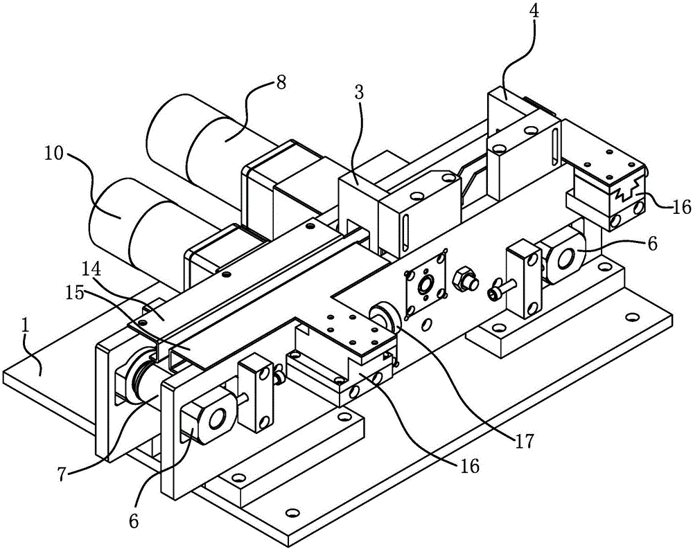
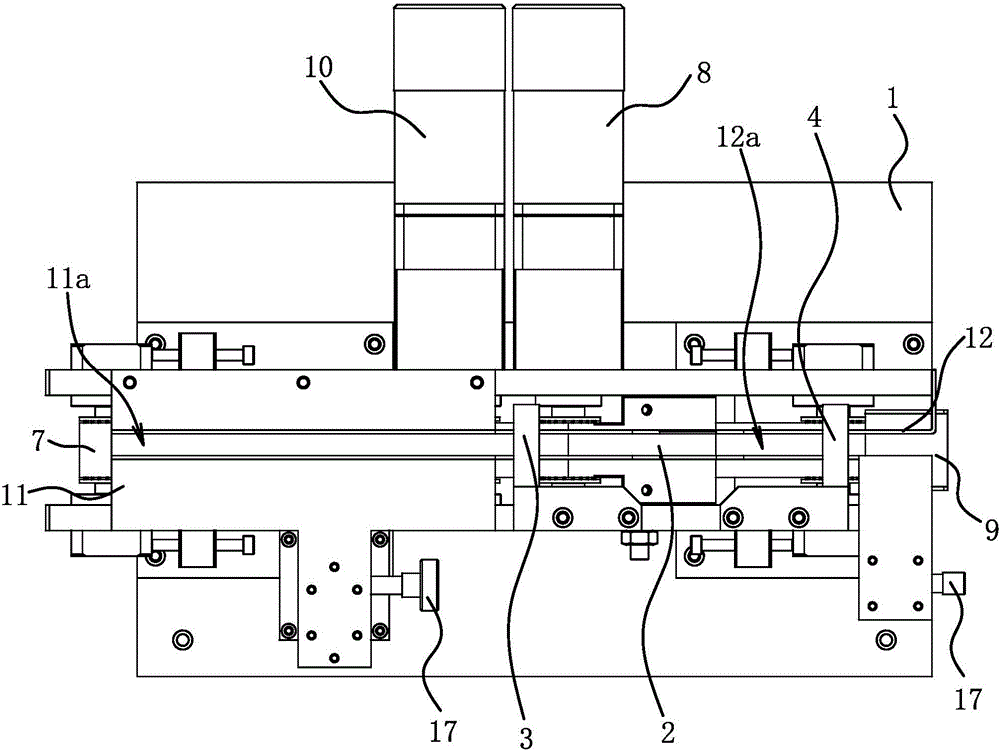
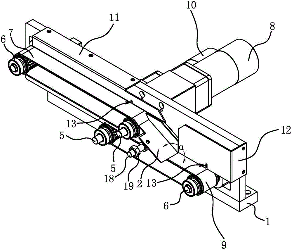
[0026] Such as Figure 1 to Figure 3 As shown, the diamond cutter head counting device includes a base 1, a first-level cutter head horizontal transmission structure, a second-level cutter head horizontal transmission structure, a swash plate 2, a first-level counting sensor 3, a second-level counting sensor 4 and a host computer.

[0027] The base 1 is the basic part of the diamond cutter head counting device, the base 1 can be fixed on the support, and the vibrating plate is also installed on the support.

[0028] The horizontal transmission structure of the primary cutter head and the horizontal transmission structure of the secondary cutter head are roughly the same, both including a transmission belt, a driving wheel 5, a tensioning wheel 6 and a servo motor; the driving wheel 5 and the tensioning wheel 6 are positioned on the base 1, The transmission belt is tensioned by the driving pulley 5 and the tensioning pulley 6, the housing of the servo motor is fixed on the base...

Embodiment 2

[0038] The structure and principle of this embodiment are basically the same as those of Embodiment 1. The basic similarities will not be described redundantly, and only the differences will be described. The differences lie in the control strategy of the diamond tip counting device. Specifically, the control strategy of the diamond cutter head counting device adopts a fixed total and difference control strategy:

[0039] First input the total number of workpieces to be counted in the host computer, such as 100; the set difference between the counting value of the primary counting sensor 3 and the counting value of the secondary counting sensor 4, such as 1.

[0040] Then control the first-level servo motor 8 and the second-level servo motor 10 to start counting, the vibrating disc will input the diamond cutter head into the first-level conveying channel 11a, and the first-level transmission belt 7 will convey the cutter head to the swash plate 2, and the cutter head will move ...


PUM


Abstract

The invention provides a diamond cutter head counting device and a diamond cutter head counting device control strategy, and belongs to the technical field of physics. The diamond cutter head counting device and the diamond cutter head counting device control strategy solve the problem of great work intensity of the existing method for manually counting diamond cutter heads. The diamond cutter head counting device comprises a base and a host machine, wherein a primary cutter head horizontal transmission structure provided with a primary conveying belt is arranged on the base, a primary protection plate forming a primary conveying passage is arranged above the primary conveying belt, the outlet end part of the primary conveying passage is provided with a primary counting sensor used for detecting the number of workpieces passing through the outlet end of the primary conveying passage, the primary counting sensor is electrically connected with the host machine, and the primary protection plate and the primary counting sensor are respectively and fixedly arranged on the base. During the monitoring, the diamond cutter head counting device adopts the cutter head horizontal conveying structure for conveyance, the cutter heads are enabled to pass through the counting sensor in a stably moving way, the long-time staying of the cutter heads is avoided, and the problem of repeated counting due to reverse movement of the cutter heads is particularly avoided.

Description

technical field [0001] The invention belongs to the technical field of physics, and relates to a counting device, in particular to a diamond cutter head counting device. [0002] The invention belongs to the technical field of physics, and relates to a counting device, in particular to a control strategy for a diamond cutter head counting device. Background technique [0003] The diamond cutter head is the main body of the diamond saw blade; the diamond cutter head needs to be counted in the processing and packaging processes. At present, the number of diamond cutter heads is mainly calculated by manual counting or weighing. Manual counting has the problems of high labor intensity and prone to errors; weighing conversion has the problem of low accuracy. Contents of the invention [0004] The invention proposes a diamond cutter head counting device, and the technical problem to be solved by the invention is how to reduce labor intensity and improve counting accuracy. [...

Claims


Application Information

Patent Timeline
Patent Type & Authority Patents(China)
IPC IPC(8): B65B65/08B65B57/20
CPCB65G43/08B65G2203/0241B65G2203/044B65G2811/093
Inventor 项俊俊
Owner TIANJIN JINHANG COMP TECH RES INST
Why Eureka
Try Eureka