
Belt conveyor capable of being horizontally bent

A conveyor and curved belt technology, applied in the direction of conveyor, conveyor objects, transportation and packaging, etc., can solve the problems of reduced recovery rate, limited increase, complicated steps, etc., to reduce the loss, wear and tear of edge coal. The effect of small size and simplified transportation system

Inactive Publication Date: 2015-05-06
赵开
View PDF13 Cites 2 Cited by
  • Summary
  • Abstract
  • Description
  • Claims
  • Application Information

AI Technical Summary

Problems solved by technology

[0003] (1) The adaptability of the transportation in the bending stage is poor
The traditional belt conveyor can only be used for the straight section or the conveying section with a small bending angle. When it is used for the section with a large bending angle or a large number of bendings, it needs to be transferred from one conveyor to another. Reloading increases the link in the transportation, and in the conveyor system, the feeding speed must be specified in some places
In addition, the traditional conveyor cannot meet the needs of fully mechanized mining face inclination adjustment, and has poor adaptability to geological conditions. Some corner coal cannot be mined, resulting in a large loss of coal, reducing the recovery rate, and no good economic benefits.
[0004] (2) The service life of the belt is short
As long as there is one damage on the conveyor belt, the belt must be replaced, but the cost of the conveyor belt is about half of the cost of the conveyor, which is very expensive; or cut off and re-spliced ​​by hot vulcanization, but the steps are cumbersome, time-consuming and labor-intensive, and re-splice The strength of the rear belt is reduced, it is more likely to be damaged, and there are safety hazards
[0005] (3) Limited transportation capacity
The traditional belt conveyor is based on the principle of friction transmission. When the transmission distance is too large, it is easy to cause the conveyor to be overloaded, and there will be slippage between the belt and the pulley, which will cause the transmission to fail.
Forcibly increasing the conveying capacity and increasing the tension of the belt will inevitably greatly accelerate the damage to the shaft of the drive roller, and the belt will wear faster, and the increase is very limited
[0006] (4) The length of the conveyor belt is not adjustable
Traditional belt conveyors generally change the length of the conveyor through a belt storage device. The belt storage device has a complex structure and a large volume, which is inconvenient for transportation and disassembly, and is not easy to relocate.
In addition, due to the limited length of the conveyor belt stored in the belt storage bin, when advancing coal mining or roadway excavation, there is a great requirement for the retractable length of the conveyor, the belt storage capacity is often not required for work, and the belt needs to be increased unnecessarily trouble, also reduces the strength of the belt
[0007] (5) easy to deviate
When the conveyor belt is running, the deviation of the conveyor belt may be caused by the deviation of the conveyor belt, eccentric accumulation of materials, deformation of the frame, wind load and uneven tension distribution.
The deviation of the conveyor belt will cause the friction between the conveyor belt and the frame, causing the edge rubber to wear
Deviation will lead to an increase in the number of accidental stops of the conveyor, affecting production, and deviation may also cause materials to spread out, reducing the operating economy of the conveyor system

Method used


Image

  • Belt conveyor capable of being horizontally bent
  • Belt conveyor capable of being horizontally bent
  • Belt conveyor capable of being horizontally bent

Examples


Embodiment Construction

[0041] Below in conjunction with accompanying drawing and embodiment the present invention will be further described:

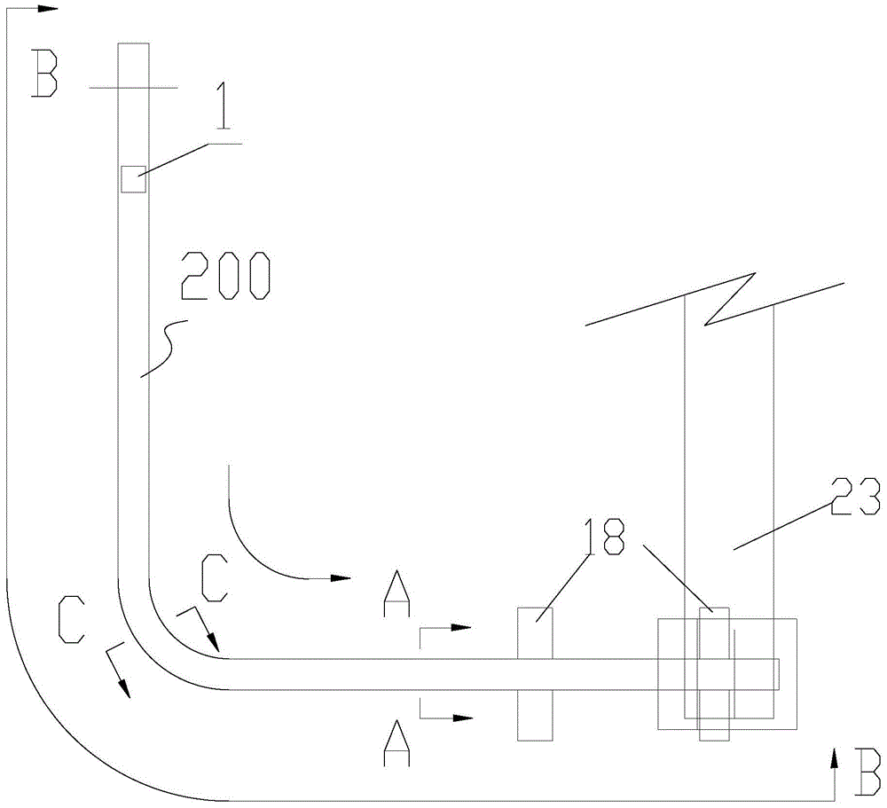
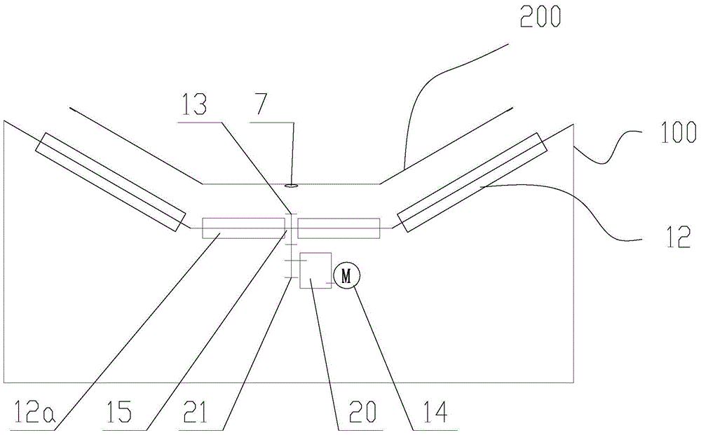
[0042] Such as figure 1 , figure 2 with image 3 As shown, a horizontally bendable belt conveyor includes a frame 100, a conveyor belt 200 and an idler roller set 300 arranged below the conveyor belt. One end of the conveyor belt is provided with a loading device 1 and the other end is provided with an unloading device 2 . Near the unloading device 2 side, a cleaning device 18 is arranged below the conveyor belt.

[0043] Such as Figure 5 to Figure 7 As shown, the conveyor belt is a multi-section split structure, each section of the conveyor belt includes a rectangular body 3, the tail of the body is symmetrically extended with a fan-shaped rack mounting part 4, and the second rack mounting part 4 is provided with a fan-shaped concentric I-shaped The front end of the rack 5 is provided with an I-shaped tooth groove 6 corresponding to the rack 5 .

[0...


PUM


Abstract

The invention discloses a belt conveyor capable of bending horizontally. The belt conveyor capable of bending horizontally comprises a machine frame, a conveyor belt and a carrier roller set arranged below the conveyor belt. The conveyor belt is of a multi-section split structure. Each section of conveyor belt comprises a rectangular body, wherein the left portion and the right portion of the tail of the body symmetrically extend to form sector gear rail installation parts, the two gear rail installation parts are provided with sector concentric gear rails, the front end of the body is provided with gear grooves corresponding to the gear rails, and the center of the bottom of the body is provided with a transmission chain. The carrier roller set comprises a buffering carrier roller, a flat carrier roller and a groove-shaped carrier roller. A turning carrier roller is arranged at the turning position of the conveyor belt. The turning carrier roller is of a groove-shaped carrier roller structure, and an outer side carrier roller of the turning carrier roller is higher than an inner side carrier roller of the turning carrier roller. The outer side carrier roller and the inner side carrier roller are provided with gears matched with a side chain. At the turning position, the specific value of radii of turning circles at different positions of the conveyor belt is equal to the specific value of radii of the carrier rollers corresponding to the positions of the conveyor belt. The belt conveyor is capable of bending, reliable in operation, low in power consumption and high in adaptability for a conveying line.

Description

technical field [0001] The invention relates to a conveyor, in particular to a belt conveyor. Background technique [0002] In the prior art, a belt conveyor mainly includes a conveyor belt, idler rollers and an intermediate frame, a roller tensioning device, a braking device, a cleaning device, and a discharge device. Conveyor belts are the most expensive and wear-resistant of the belt conveyor components. When transporting highly abrasive materials, such as iron ore, the durability of the conveyor belt is significantly reduced. The traditional belt conveyor mainly has the following problems in mine production: [0003] (1) The adaptability of the transportation in the bending stage is poor. The traditional belt conveyor can only be used for the straight section or the conveying section with a small bending angle. When it is used for the section with a large bending angle or a large number of bendings, it needs to be transferred from one conveyor to another. Reloading i...

Claims


Application Information

Patent Timeline
Patent Type & Authority Applications(China)
IPC IPC(8): B65G15/30B65G15/62B65G39/18
CPCB65G15/30B65G15/62B65G39/18B65G2812/02168B65G2812/02217
Inventor 赵开
Owner 赵开
Learn More