
Treatment device and treatment technology for denitration catalyst cleaning regeneration wastewater and waste residue

A technology for denitrification catalysts and regenerated wastewater, which is applied in the directions of water/sewage multi-stage treatment, water/sludge/sewage treatment, and the use of liquid separation agents. Achieve the effect of process environmental protection, low cost and high dust removal efficiency

Active Publication Date: 2015-05-06
HUADIAN ELECTRIC POWER SCI INST CO LTD
View PDF4 Cites 9 Cited by
  • Summary
  • Abstract
  • Description
  • Claims
  • Application Information

AI Technical Summary

Problems solved by technology

For example, the Chinese patent whose publication date is 2013-01-09 and whose publication number is CN102861621A discloses a removable SCR denitrification catalyst cleaning and regeneration device and cleaning and regeneration method; another example is 2014-10-01, whose publication number is In the Chinese patent CN104069900A, a cleaning method and device for regeneration of waste denitrification catalysts are disclosed; another example is a Chinese patent with publication date of 2014-10-08 and publication number CN203862254U, which discloses a SCR denitrification catalyst Cleaning and regeneration devices, etc.; however, looking at all catalyst regeneration technologies, only research on how to regenerate catalysts has been conducted, but no explanation has been given on how to treat the wastewater generated during the catalyst regeneration process, ignoring the treatment of catalyst regeneration wastewater

Method used


Image

  • Treatment device and treatment technology for denitration catalyst cleaning regeneration wastewater and waste residue

Examples


Embodiment 2

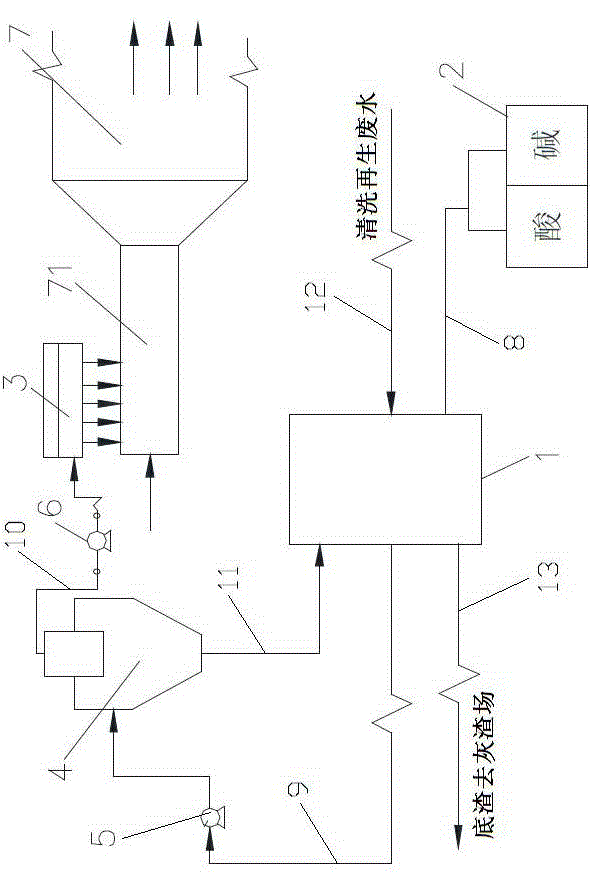
[0035] see figure 1 , the denitrification catalyst of the present embodiment cleans and regenerates the treatment device of waste water slag by waste water buffer sedimentation tank 1, acid-base dosing tank 2, ultrasonic atomizing nozzle 3, waste water cyclone 4, No. 1 liquid delivery pump 5, No. 2 liquid It consists of delivery pump 6, dust collector 7, acid-base supply pipe 8, supernatant liquid delivery pipe 9, overflow filtrate delivery pipe 10, underflow return pipe 11, cleaning and regeneration waste water delivery pipe 12 and bottom slag delivery pipe 13. The connection relationship between them is the same as that in Example 1. The processing device in this embodiment can be manufactured as an integrated mobile device, and the integrated mobile device can be transported to the site of the denitrification catalyst cleaning and regeneration project by water or land transportation. Wastewater treatment saves time and effort.

[0036] The specific implementation process o...


PUM


Abstract

The invention relates to a treatment device and a treatment technology for denitration catalyst cleaning regeneration wastewater and waste residue. A treatment device and a treatment technology for denitration catalyst cleaning regeneration wastewater and waste residue, which have high energy utilization rate and can realize recycling of the denitration catalyst cleaning regeneration wastewater, are unavailable now. The treatment device is characterized by comprising a wastewater buffer sedimentation tank, an acid-base dosing box, an ultrasonic atomizing nozzle, a wastewater hydrocyclone, a liquid conveying pump, a deduster, an acid-base supply pipe and an underflow return pipe, wherein a cleaning regeneration wastewater conveying pipe and a bottom residue conveying pipe are both connected to the wastewater buffer sedimentation tank; and the acid-base dosing box is connected to the wastewater buffer sedimentation tank through the acid-base supply pipe. The treatment technology comprises the following steps: conveying the denitration catalyst cleaning regeneration wastewater into the wastewater buffer sedimentation tank; adjusting the pH value; standing for sedimentation; performing solid-liquid separation of the supernate; and atomizing the overflow filtrate and spraying into the deduster. The treatment device and treatment technology provided by the invention can be used for realizing recycling of the denitration catalyst cleaning regeneration wastewater.

Description

technical field [0001] The invention relates to a treatment device and process for waste water and waste residue, in particular to a treatment device and process for cleaning regenerated waste water and waste residue with a denitrification catalyst, and belongs to the technical fields of air pollution control technology and water pollution control technology. Background technique [0002] With the increasingly stringent national environmental protection policies, domestic thermal power units in service and new thermal power units are equipped or plan to be equipped with denitrification devices to ensure that NO in flue gas X Discharge. The Selective Catalytic Reduction (SCR) denitrification process is widely used in the denitrification system of coal-fired power plants because of its high efficiency, reliability and stable performance. One of the core technologies of this process is the use of denitrification catalysts. [0003] The denitrification catalyst has the problem ...

Claims


Application Information

Patent Timeline
Patent Type & Authority Applications(China)
IPC IPC(8): C02F9/10B01D47/06
Inventor 朱跃杨用龙王丰吉蒋志强张杨晋银佳
Owner HUADIAN ELECTRIC POWER SCI INST CO LTD
Learn More