Spaced staggered reverse deflecting flow energy dissipation hydraulic rectifying device and method

A rectification device and staggered technology, which is applied in the field of interval staggered reverse deflection energy dissipation hydraulic rectification devices, can solve the problems of unstable water flow, sediment deposition, etc., and achieve the prevention and control of sediment deposition, increased flow velocity, The effect of increasing the bottom flow velocity

Inactive Publication Date: 2015-05-06
NORTH CHINA UNIV OF WATER RESOURCES & ELECTRIC POWER
View PDF5 Cites 5 Cited by
  • Summary
  • Abstract
  • Description
  • Claims
  • Application Information

AI Technical Summary

Problems solved by technology

[0006] The purpose of the present invention is to overcome the defects of the above-mentioned technologies, and to provide a spaced and staggered reverse deflection energy-dissipating hydraulic rectification device and method, which can effectively solve the problem of water flow in the forebay and the inlet pool during the operation of the gate-controlled pumping station. Problems with fluid instability and sedimentation

Method used


Image

  • Spaced staggered reverse deflecting flow energy dissipation hydraulic rectifying device and method
  • Spaced staggered reverse deflecting flow energy dissipation hydraulic rectifying device and method
  • Spaced staggered reverse deflecting flow energy dissipation hydraulic rectifying device and method

Examples


Embodiment 1

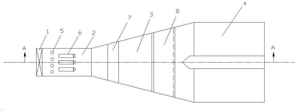
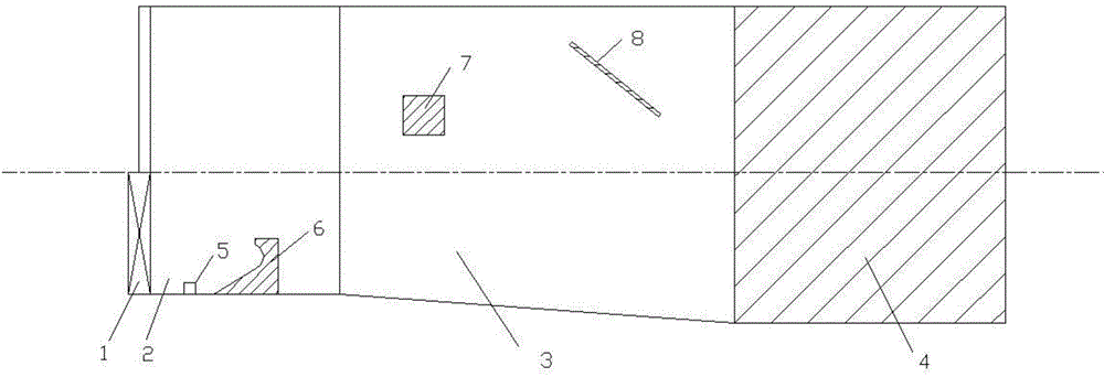
[0031] refer to Figure 1-Figure 2 , a spaced staggered reverse deflected flow energy dissipation hydraulic rectification device, comprising a gate 1, aqueduct 2, a forebay 3, an inlet pool 4, an interval type bottom sill 5, an interval type reverse deflected flow energy dissipation pier 6, rectification Beam 7 and pressure water plate 8.

[0032] The spaced bottom sill 5 is arranged behind the gate 1, and the height of the spaced bottom sill 5 is lower than the opening of the gate 1. The spaced bottom sill 5 is symmetrically distributed on the center line of the aqueduct 2, and the two spaced bottom sills 5 The interval dimension and the quantity of the interval type bottom sill 5 are determined according to the width of the aqueduct 2 . The spaced bottom sill 5 is a cylinder with a circular horizontal section. The spaced reverse deflecting flow energy dissipation pier 6 is arranged symmetrically in a staggered manner with the spaced bottom sill 5 along the centerline of th...

Embodiment 2

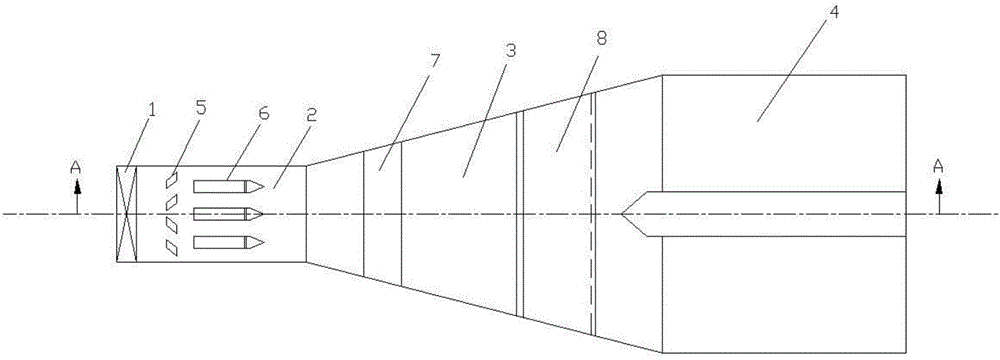
[0040] refer to Figure 3-Figure 4 , a spaced staggered reverse deflected flow energy dissipation hydraulic rectification device, comprising a gate 1, aqueduct 2, a forebay 3, an inlet pool 4, an interval type bottom sill 5, an interval type reverse deflected flow energy dissipation pier 6, rectification Beam 7 and pressure water plate 8.

[0041] The spaced bottom sill 5 is arranged behind the gate 1, and the height of the spaced bottom sill 5 is lower than the opening of the gate 1. The spaced bottom sill 5 is symmetrically distributed on the center line of the aqueduct 2, and the two spaced bottom sills 5 The interval dimension and the quantity of the interval type bottom sill 5 are determined according to the width of the aqueduct 2 . The spaced bottom sill 5 is a quadrangular prism with a parallelogram in horizontal section. The spaced reverse deflecting flow energy dissipation pier 6 is arranged symmetrically in a staggered manner with the spaced bottom sill 5 along th...


PUM


Abstract

The invention discloses a spaced staggered reverse ski-pump energy dissipation hydraulic rectifying device and method. The device comprises a gate, a diversion canal, a front pool, an intake pool, spaced bottom sills, spaced reverse deflecting flow energy dissipation piers, a rectifying beam and a depressed plate, wherein the spaced bottom sills are arranged behind the gate, and are distributed symmetrically along the center line of the diversion canal; the spaced reverse deflecting flow energy dissipation piers are arranged behind the spaced bottom sills, and are distributed symmetrically with the spaced bottom sills in a staggered way along the center line of the diversion canal, and the quantity of the spaced reverse deflecting flow energy dissipation piers is one less than that of the spaced bottom sills; the upstream faces of the spaced reverse deflecting flow energy dissipation piers are reverse water current circular-arc curved surfaces, the longitudinal sections are reverse water current circular-arc curves, and the horizontal sections are rectangular; the rectifying beam is distributed at the front end of the front pool; the depressed plate is arranged at the back end of the front pool. The spaced bottom sills and the spaced reverse deflecting flow energy dissipation piers can be applied to different diversion projects as different combinations.

Description

technical field [0001] The invention belongs to the technical field of water conservancy engineering, and relates to an interval and staggered reverse deflecting flow energy dissipation hydraulic rectification device and method. Background technique [0002] Due to the limitation of water diversion conditions and geographical location, many pump stations in my country, especially the Yellow River Diversion Pump Station, need gates to control water diversion during operation, forming a jet flow under the gate and rushing directly into the forebay, inlet pool and pump room, resulting in deterioration of the flow state and bringing A series of problems such as cavitation, sediment deposition, strong vibration of the unit and the pump room, reduced efficiency of the pump station, and reduced operating benefits, etc., and as the water level in front of the sluice rises, the operating characteristics of the forebay and the inlet pool also change. This further led to unstable operati...

Claims


Application Information

Patent Timeline
Patent Type & Authority Applications(China)
IPC IPC(8): E02B8/06
CPCE02B8/06
Inventor 高传昌汪顺生张亮李君周文高志锴刘玉龙
Owner NORTH CHINA UNIV OF WATER RESOURCES & ELECTRIC POWER
Why Eureka
Try Eureka