A variable-diameter stabilizer that can be controlled on the ground

A stabilizer and ground technology, applied to drilling equipment, earthwork drilling, drill pipe, etc., can solve the problems of reducing drilling time efficiency, scraping, long adjustment period, etc., and achieve improved drilling time efficiency, simple device structure and convenient operation Effect

Active Publication Date: 2017-01-04
中国石油集团川庆钻探工程有限公司长庆钻井总公司
View PDF6 Cites 0 Cited by
  • Summary
  • Abstract
  • Description
  • Claims
  • Application Information

AI Technical Summary

Problems solved by technology

[0004] 1. When the tripping is not smooth, it is easy to encounter obstacles and jams, which will induce drilling accidents;
[0005] 2. When the diameter wears down to a certain extent, it will all be scrapped, which increases the drilling cost;
[0006] Three, when the enlarged wellbore section works, the drill pipe cannot be effectively stabilized;
[0007] Fourth, because the adjustment period is long, the wellbore trajectory will show a "fluctuating" type, which will generate additional torque and resistance. Conventional drilling tools cannot adapt to the current complex drilling technology requirements such as directional wells or horizontal wells.
[0008] Moreover, using the traditional fixed stabilizer, because of its fixed structure, the replacement of the stabilizer must be realized by tripping, which increases the auxiliary time of drilling operations
When the fixed stabilizer is used in tripping and directional working conditions, there are technical problems such as reaming when encountering resistance, deflection prevention in easily deviated formations, wellbore trajectory control in directional wells, and increased mechanical speed, which may easily cause scraping of the wellbore wall and The "piston pulling" phenomenon increases the soaking time of the mud on the well wall, prolongs the drilling construction period, reduces the drilling efficiency, and even causes the well wall to become unstable, resulting in complex downhole accidents such as well collapse and blowout

Method used


Image

  • A variable-diameter stabilizer that can be controlled on the ground
  • A variable-diameter stabilizer that can be controlled on the ground
  • A variable-diameter stabilizer that can be controlled on the ground

Examples


Embodiment 1

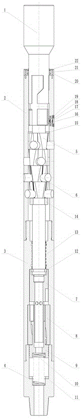
[0041] This embodiment provides a variable diameter stabilizer that can be controlled on the ground, such as Figures 1 to 5 As shown, it includes a tubular casing, the casing is equipped with a central shaft 1, and the casing is composed of an upper casing 2, a middle casing 3 and a lower casing 4 connected in sequence,

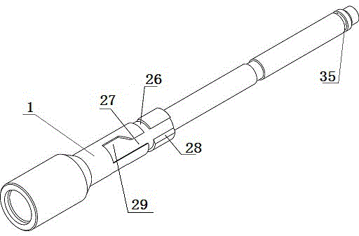
[0042] The upper part of the central shaft 1 is provided with a self-locking groove, and the middle part of the central shaft 1 is fixed with a tapered sleeve 5;

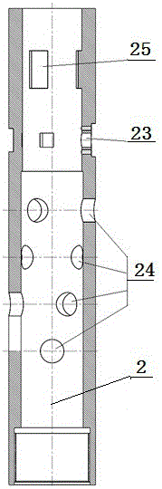
[0043] The upper part of the upper housing 2 is provided with a lock block square hole 23, and a self-locking device is installed in the lock block square hole 23. The inner end of the self-locking device corresponds to the self-locking groove on the central axis 1; the lower part of the upper housing 2 is along the circumferential direction There are a plurality of cylindrical holes 24 distributed in the axial direction. The cylindrical holes 24 are equipped with stabilizing columns 6 , and the i...

Embodiment 2

[0049] On the basis of Embodiment 1, the self-locking device in the lock block square hole 23 in this embodiment is made up of a self-lock block 16, a self-lock spring 17, a spring pressing plate 18 and a fastening screw 19, and the fastening screw 19 presses the spring pressing plate 18 is fixed in the square hole 23 of the locking block, the self-locking spring 17 and the self-locking block 16 are positioned at the inner side of the spring pressing plate 18, and the two ends of the self-locking spring 17 are respectively fixed on the spring pressing plate 18 and the self-locking block 16, and the self-locking block 16 The bottom end face is arc-shaped, such as Figure 11As shown, the self-locking block 16 is a cube structure, one end face is arc-shaped, one corner of the arc-shaped end face is cut off, and the other end face is provided with a cylindrical spring hole for installing the self-locking spring 17 .

[0050] A rectangular protrusion 25 is also provided on the inne...

Embodiment 3

[0056] In Embodiment 1, the stabilizing post 6 will move radially along with the axial movement of the tapered sleeve 5. In this embodiment, as Image 6 with Figure 7 As shown, the upper end surface of the stabilizing column 6 is an arc surface, and the lower end surface is a conical plane with a dovetail groove 30 .

[0057] In this embodiment, the dovetail groove 30 and the dovetail block track 31 are used to cooperate to connect the stabilizing post 6 to the tapered sleeve 5. With the axial movement of the tapered sleeve 5, the stabilizing post 6 moves on the tapered surface. The dovetail block track 31 on the sleeve 5 slides and moves radially.

[0058] In this embodiment, the tapered sleeve 5 may also be spliced ​​by several tapered sleeves fitted on the central shaft 1 sequentially in the axial direction.

[0059] Further, the plurality of cylindrical holes 24 are distributed in a helical shape along the axial direction at the lower part of the upper casing 2 , and th...


PUM


Abstract

The invention belongs to the technical field of a downhole tool and particularly relates to a variable-diameter stabilizer capable of being controlled on the ground. The variable-diameter stabilizer comprises a pipe-shaped shell, wherein a central shaft is arranged in the shell; a self-locking groove is formed in the upper part of the central shaft; a tapered sleeve sleeves the middle part of the central shaft; a locking block square hole is formed in the upper part of the shell; a self-locking device is arranged in the locking block square hole; the inner end of the self-locking device corresponds to the self-locking groove in the central shaft; a plurality of cylindrical holes are uniformly formed in the shell along the peripheral direction and the axial direction; stabilization columns are arranged in the cylindrical holes; the inner ends of the stabilization columns are located on the outer wall of the tapered sleeve. According to the variable-diameter stabilizer capable of being controlled on the ground, the aim that the stabilizers with different outer diameter sizes are utilized in different well sections is realized. Meanwhile, the outer diameter conversion is realized by different ground operations and a control unit does not need to be specially and additionally arranged; the link that an existing non-electric-control variable-diameter stabilizer needs to control pump pressure or count the times of switching on and off a pump is overcome; the operation is simplified, the structure is simple, the operation is convenient and the well drilling timeliness is improved.

Description

technical field [0001] The invention belongs to the technical field of downhole tools, and relates to a variable stabilizer used in oil drilling directional wells, horizontal wells and extended displacement drilling operations, in particular to a variable diameter stabilizer that can be controlled on the ground. Background technique [0002] In the drilling construction of directional wells, horizontal wells and extended-reach wells, in order to control and adjust the wellbore inclination, it is usually stabilized by using drill pipes of different sizes and lengths, weighted drill pipes, drill collars, etc. Drill tool assembly for deflection building, deflection stabilization or deflection declination. [0003] Conventionally used drill stabilizers are integral, and the diameter is fixed and cannot be changed, generally 2mm smaller than the drill bit, which has four main disadvantages: [0004] 1. When the tripping is not smooth, it is easy to encounter obstacles and jams, ...

Claims


Application Information

Patent Timeline
Patent Type & Authority Patents(China)
IPC IPC(8): E21B17/10
CPCE21B17/10
Inventor 杨森宋顺平李培梅王强
Owner 中国石油集团川庆钻探工程有限公司长庆钻井总公司
Why Eureka
Try Eureka