
Mining supporting support equipment and mining method thereof

A kind of equipment and the technology of coal mining machine, which is applied in the supporting support equipment for coal mining and its coal mining field, can solve the problems that the top coal cannot be recovered, the heat is easy to accumulate, and the air leakage in the goaf is large, so as to avoid the natural phenomenon of high temperature, Avoid too many omissions and the effect of avoiding resource waste

Active Publication Date: 2015-05-06
CHINA SHENHUA ENERGY CO LTD +1
View PDF7 Cites 6 Cited by
  • Summary
  • Abstract
  • Description
  • Claims
  • Application Information

AI Technical Summary

Problems solved by technology

Especially the top coal along the goaf is left in the goaf in a broken state, and the place along the goaf is the place where heat is most likely to accumulate and the air leakage in the gob is the largest, and spontaneous combustion is most likely to occur, posing a huge hidden danger
[0008] At present, major domestic coal enterprises have successively arranged large mining height working faces, and gradually appeared 3.5m, 4.0m, 4.5m, 5.0m, 5.5m, 6.3m, 7m, 7.2m and other fully mechanized mining working faces with large mining heights. When tunneling in the fully mechanized mining face with large mining height, it is basically excavated along the coal seam floor. The roadway excavation height is not as large as the thickness of the coal seam. During the mining process, the top coal cannot be recovered along the tunnel, and all of it will be left in the goaf after collapse. The waste of coal resources is avoided, and on the other hand, the high temperature in the goaf naturally buries hidden dangers.

Method used


Image

  • Mining supporting support equipment and mining method thereof
  • Mining supporting support equipment and mining method thereof
  • Mining supporting support equipment and mining method thereof

Examples


Embodiment Construction

[0065] The specific implementation manner of the present invention will be further described below in conjunction with the accompanying drawings. Wherein the same components are denoted by the same reference numerals. It should be noted that the words "front", "rear", "left", "right", "upper" and "lower" used in the following description refer to the directions in the drawings, and the words "inner" and "outer ” refer to directions towards or away from the geometric center of a particular part, respectively.

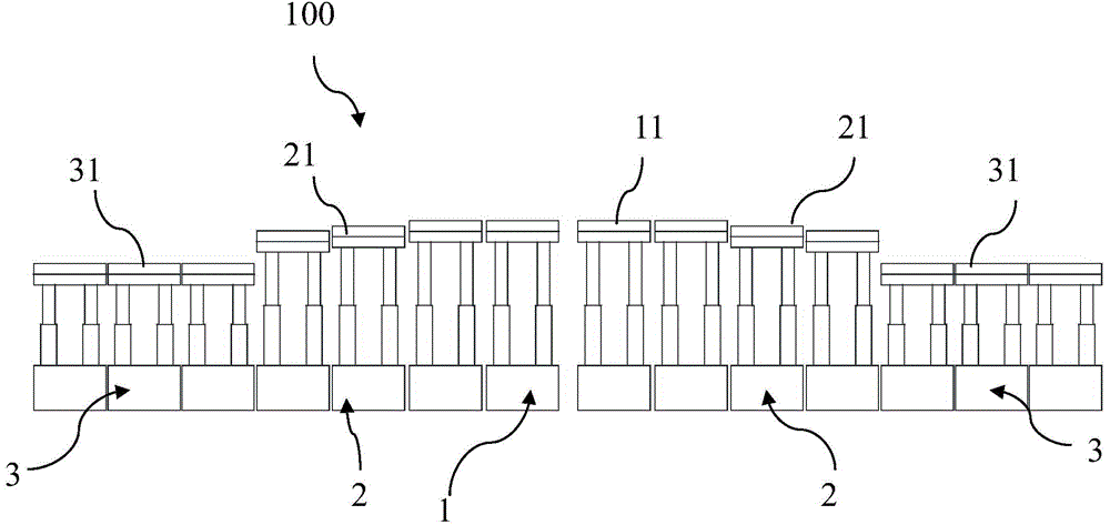
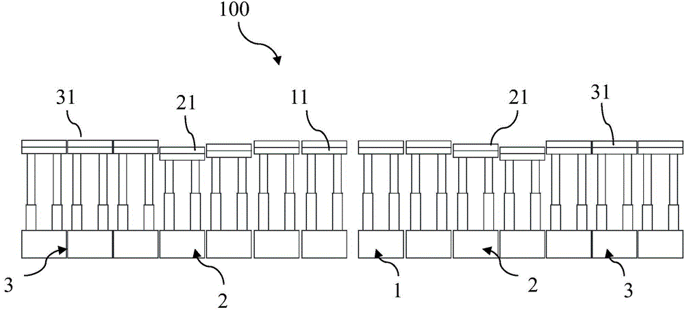
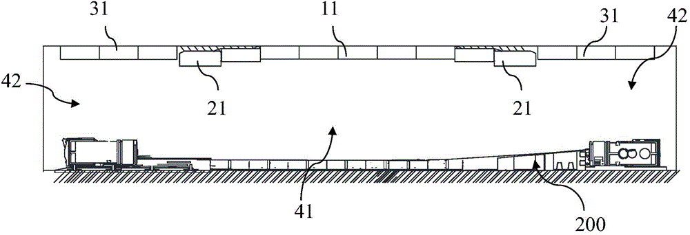
[0066] Such as Figure 1-4 As shown, the present invention provides a support support device 100 for coal mining, which includes an intermediate hydraulic support device 1 installed in a coal mining roadway 41 for supporting the roof of a coal mining face and a trough located at both ends of the coal mining roadway 42, the terminal hydraulic support device 3 used to support the roof of the trough, the two ends of the middle hydraulic support device 1 are respectively p...


PUM


Abstract

The invention discloses mining supporting support equipment which comprises a middle hydraulic support device and end hydraulic support devices, wherein the middle hydraulic support device is used for supporting a mining working surface top plate, the end hydraulic support devices are located in troughs in two ends of a mining roadway and used for supporting the ends of a trough plate, the end hydraulic support devices are arranged at two ends of the middle hydraulic support devices respectively, a transition hydraulic support device is arranged between the end hydraulic support device at each end and the middle hydraulic support device, height of the middle hydraulic support device supporting top end of the middle hydraulic support device, the transition hydraulic support device supporting top end of the transition hydraulic support device and the end hydraulic support device supporting top ends of the end hydraulic support devices can be adjusted in the vertical direction, and the middle hydraulic support device supporting top end and the end hydraulic support device supporting top ends are arranged in flush. The invention further discloses a mining method used for the mining supporting support equipment to mine trough top coal in a fully mechanized coal mining face.

Description

technical field [0001] The invention relates to the technical field of coal mining in coal mines, in particular to a support bracket device for coal mining and a coal mining method thereof. Background technique [0002] A fully mechanized mining face is basically composed of a shearer, a conveyor, a loader, a crusher, and a belt conveyor. During coal mining, support equipment is required to support the roof to avoid coal seam collapse and construction danger. [0003] The side of the fully mechanized mining face close to the belt conveyor is often called the "head", and the other side is called the "tail". The support equipment currently used is generally a gentle transition or a vertical transition on the tail side, resulting in a part of the coal on the roof of the chute that cannot be mined. [0004] At present, in view of the fact that the mining height of the working face is greater than the height of the trough in the world, there are two techniques for cutting coal ...

Claims


Application Information

Patent Timeline
IPC IPC(8): E21D23/00E21C41/18
CPCE21C41/18E21D23/04E21D23/16
Inventor 张立辉杨俊哲迟国铭孙权刘兆祥张永福
Owner CHINA SHENHUA ENERGY CO LTD
Learn More