
Sunlight direct illumination system and control method thereof

A lighting system and sunlight technology, which is applied to the control system of a directional light guide and its control field, can solve problems such as the inability to guarantee sunlight transmission and the inability of the closed-loop automatic control system to work normally.

Active Publication Date: 2015-05-06
SHAANXI UNIV OF SCI & TECH
View PDF11 Cites 14 Cited by
  • Summary
  • Abstract
  • Description
  • Claims
  • Application Information

AI Technical Summary

Problems solved by technology

However, for the signal collector in the closed-loop control system of the fiber-free sunlight conveyor, because of the change of the working environment (installed in the tunnel), the rough adjustment function has been lost - looking for targets in a large range
The main reason is that the sunlight collection sensor is installed on the optical path of directional reflection sunlight in the tunnel, and its optical axis is parallel to the center line of the tunnel, so once the sun just comes out in the morning or the sun just comes out of the cloud Under such circumstances, the light guide cannot guarantee that the sunlight will be immediately transported into the optical path designed in the arch space above the tunnel, so that the sunlight signal collection sensor installed here can ensure that the system enters an ideal working state after collecting the signal, while The above two special situations are inevitable objective existence, so the closed-loop automatic control system designed according to this scheme to drive the load of the light guide mirror cannot work normally in practical applications

Method used


Image

  • Sunlight direct illumination system and control method thereof
  • Sunlight direct illumination system and control method thereof
  • Sunlight direct illumination system and control method thereof

Examples


Embodiment Construction

[0033] Combine below Attached picture The present invention is described in further detail:

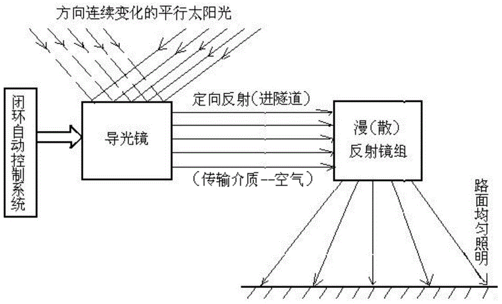
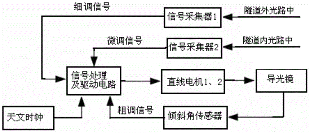
[0034] see Figure 5 , the solar direct lighting system of the present invention comprises the first signal collector 5 and the second signal collector 6 arranged on the reflected light path of the light guide 7, which can pass through the light guide 7 at the exit of the tunnel, and set Several reflecting mirror groups 9 and control modules at the top of the tunnel; the light guide 7 is provided with a light reflecting surface and a linear motor for controlling the direction of the light reflecting surface, and the light reflecting surface back of the light guide 7 is also provided with There is an inclination sensor 8; the inclination sensor 8, the first signal collector 5 and the second signal collector 6 are connected to the control module; the linear motor of the light guide 7 is also connected to the control module; the control module , the linear motor of tilt angle sensor...


PUM


Abstract

The invention discloses a sunlight direct illumination system and a control method of the sunlight direct illumination system. The sunlight direct illumination system comprises a light guider, a first signal collector, a second signal collector, a plurality of reflector sets and a control module, wherein the first signal collector and the second signal collector are arranged on a reflection light path of the light guider; the light guider is provided with a light reflection plane, a linear motor used for controlling the direction of the light reflection plane and a slant angle sensor; the slant angle sensor, the first light signal collector and the second light signal collector are connected to the control module; the linear motor of the light guider is also connected to the control module; the control module, the slant angle sensor, the first light signal collector, the second light signal collector and the linear motor of the light guider form a closed-loop control system. The sunlight direct illumination system can automatically track a signal blind region generated when the system deviates from sunlight all the time after sunlight appears and effectively solve the off-target problem as soon as possible to find a target, and therefore it is guaranteed that the system enters a normal working state.

Description

technical field [0001] The invention belongs to sunlight direct lighting equipment, and is mainly used in the field of road tunnel enhanced lighting, in particular to a control system and a control method of a directional light guide. Background technique [0002] In a common system that utilizes a sunlight conveyor to realize tunnel enhanced lighting, no matter it is a reflective or transmissive concentrator, the light receiver (such as the receiving end face of an optical fiber) is always at the focal point of the concentrator (such as a convex lens), and passes through The interface is fixed on the base frame so as to form an integral structure with the light concentrator. Therefore, in any case, as long as the high-precision control system of the two-axis automatic tracking of sunlight ensures that the optical axis of the concentrator is parallel to the incident light of the sun, the concentrated sunlight will naturally focus on the optical fiber receiving end at its foc...

Claims


Application Information

Patent Timeline
IPC IPC(8): F21S11/00F21V8/00F21V14/04H05B37/02F21W131/101
CPCF21S11/005F21S11/007F21V14/04F21W2131/101H05B47/10
Inventor 宁铎尤磊张东煜张根宝张博辛登科赵彬
Owner SHAANXI UNIV OF SCI & TECH
Features
  • Generate Ideas
  • Intellectual Property
  • Life Sciences
  • Materials
  • Tech Scout
  • Unparalleled Data Quality
  • Higher Quality Content
  • 60% Fewer Hallucinations
Learn More