FPGA (field programmable gate array)-based time-digital converter
A time-to-digital, converter technology, applied in the direction of electrical unknown time interval measurement, devices and instruments for measuring time interval, etc.
- Summary
- Abstract
- Description
- Claims
- Application Information
AI Technical Summary
Problems solved by technology
Method used
Image
Examples
Embodiment Construction
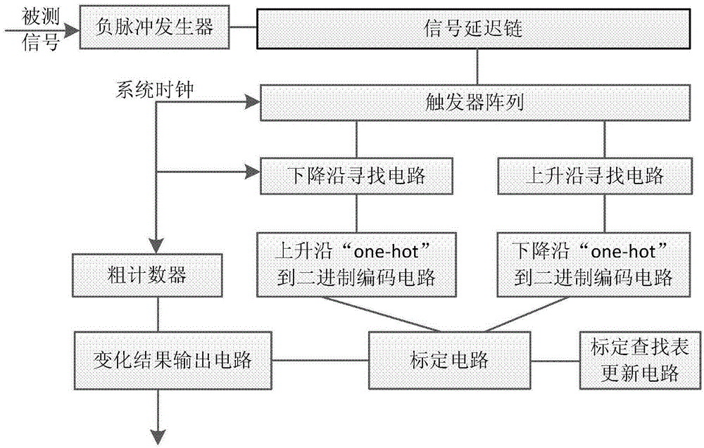
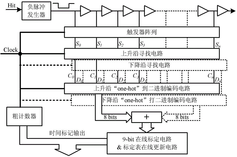
[0031] figure 1 It is a structural schematic diagram of the FPGA-based time-to-digital converter provided by the present invention. Such as figure 1 As shown, it includes a coarse clock counter, a pulse signal generator, a signal delay chain, a flip-flop array, a parallel signal rising edge search circuit and a falling edge search circuit, a parallel rising edge "one-hot" encoding circuit and a falling edge " One-hot" encoding circuit, calibration circuit and transformation result output circuit. The coarse clock counter is driven by the system clock signal and is used to generate a count signal based on the signal under test. A "one-hot" code is a code in which all but one of the bits are identical, such as ... 00001000 ..., or ... 111110111 .... The former may also be referred to as a "one-hot" code represented by "1", and the latter may also be referred to as a "one-hot" code represented by "0".
[0032] The pulse signal generator is externally triggered, which is used ...
PUM
 Abstract
Description
Claims
Application Information
 - R&D
- Intellectual Property
- Life Sciences
- Materials
- Tech Scout
- Unparalleled Data Quality
- Higher Quality Content
- 60% Fewer Hallucinations
Browse by: Latest US Patents, China's latest patents, Technical Efficacy Thesaurus, Application Domain, Technology Topic, Popular Technical Reports.
© 2025 PatSnap. All rights reserved.Legal|Privacy policy|Modern Slavery Act Transparency Statement|Sitemap|About US| Contact US: help@patsnap.com


