Alternating current electric transmission line lightning flashover restriction method and device

A technology for lightning flashover and power transmission lines, which is applied to the installation of circuits, cables, and electrical components. It can solve the problems of inconvenience in installation and construction, affect the normal power supply of lines, increase the workload of installation and construction, and achieve convenient on-site construction and lightning protection. Visible, lightweight effect

Inactive Publication Date: 2015-05-06
STATE GRID CORP OF CHINA +2
View PDF3 Cites 12 Cited by
  • Summary
  • Abstract
  • Description
  • Claims
  • Application Information

AI Technical Summary

Problems solved by technology

After research and analysis, the applicant found that the gapless line surge arrester is directly connected to the wire, and it operates with electricity for a long time. Once a fault occurs, it will directly affect the normal power supply of the line.
The new type of line arrester with "maintenance-free" function requires the installation of fault indicators, thermal explosion disconnectors and suspension auxiliary mechanisms. In addition to increasing the workload of installation and construction, it is also necessary to design special suspension auxiliary mechanisms for the structure of the tower. This will bring inconvenience to the installation and construction

Method used


Image

  • Alternating current electric transmission line lightning flashover restriction method and device
  • Alternating current electric transmission line lightning flashover restriction method and device
  • Alternating current electric transmission line lightning flashover restriction method and device

Examples


Embodiment 1

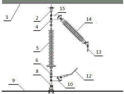
[0035] Embodiment one: if figure 1 , Figure 6 As shown, a specific structure of the device of the present invention is designed for 110kV AC transmission lines, and the limiter used to prevent lightning flashover adopts a single-string insulator lightning flashover limiter . The single-string insulator lightning flashover limiter includes a special-shaped connection device and a nonlinear energy absorption component 14, and the nonlinear energy absorption component 14 is combined with the parallel gap and the special-shaped connection device. Wherein, the special-shaped connecting device adopts a special-shaped connecting plate, and the special-shaped connecting plate includes a lower special-shaped connecting plate 10 and an upper special-shaped connecting plate 15 . The fixture of fixed insulator 5 adopts two hanging plates, which are respectively upper hanging plate 4 and lower end hanging plate 6 according to their installation positions. The upper end of the nonlinear...

Embodiment 2

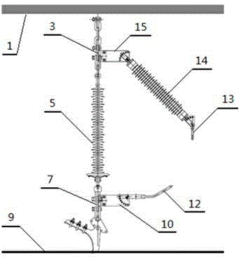
[0036] Embodiment two: if figure 2 , Figure 6 As shown, another specific structure of the device of the present invention is designed for 110kV AC transmission line, which adopts a limiter for preventing lightning flashover, and the limiter for preventing lightning flashover adopts a double-string insulator lightning flashover limiter . The double-string insulator lightning flashover limiter includes a special-shaped connecting device and a nonlinear energy absorbing component 14, wherein the special-shaped connecting device adopts two special-shaped connecting plates, which are the lower special-shaped connecting plate 10 and the upper special-shaped connecting plate 15 respectively. The two ends of the parallel gap are connected with electrodes 12 and 13 respectively, and the fixing parts of the fixed insulator 5 have adopted two connecting plates, which are respectively the upper connecting plate 3 and the lower connecting plate 7 according to the differences of the resp...

Embodiment 3

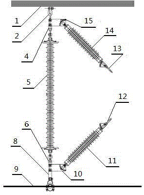
[0037] Embodiment three: as image 3 As shown, the third specific structure of the device of the present invention is designed for 220kV AC transmission lines, which adopts a limiter for preventing lightning flashover, and the limiter for preventing lightning flashover adopts a single string insulator lightning flashover limiter . The single-string insulator lightning flashover limiter includes a special-shaped connection device and a nonlinear energy absorbing component. The nonlinear energy absorbing component has two groups, and the two groups have the same structure, namely the nonlinear energy absorbing component 11 and the nonlinear energy absorbing component 14 . The fixture of fixed insulator 5 adopts two hanging plates, which are respectively upper hanging plate 4 and lower end hanging plate 6 according to their installation positions. The special-shaped connecting device adopts two special-shaped connecting plates, which are respectively a lower special-shaped conne...


PUM


Abstract

The invention relates to an alternating current electric transmission line lightning flashover restriction method and device. The method includes the steps of current steering, voltage limiting and arc blowing-out. The current steering includes the steps of providing a current discharge channel for power frequency short-circuit current through a parallel gap, wherein the parallel gap is mounted on both ends of an insulator, the breakdown strength of the parallel gap is lower than that of the insulator, and lightning current flows through the parallel gap rather than passing through the insulator when the parallel gap is broken down by lightning. The voltage limiting includes the steps of connecting a non-linear energy absorbing assembly in series with the parallel gap and limiting over-voltage at both ends of the insulator to prevent the insulator from being damaged by lightning flashover, wherein the non-linear energy absorbing assembly is used for absorbing lightning current energy on the basis of current steering. The arc blowing-out includes the steps of treating continuous combustion caused by arc produced in the parallel gap when the power frequency short-circuit current continues to flow through the parallel gap after lightning current passes to prevent tripping of a circuit breaker. The alternating current electric transmission line lightning flashover restriction device is composed of the parallel gap, electrodes, the non-linear energy absorbing assembly and a special-shaped connecting unit which are assembled and connected with one another and is simple in structure, light in weight and small in size.

Description

technical field [0001] The invention relates to the field of lightning protection of electric power systems, in particular to a lightning flashover limiting method and device for AC transmission lines. The invention is used in 110kV / 220kV AC transmission lines, can improve the reliability of transmission line operation, and can also improve the application level of lightning flashover limitation technology. Background technique [0002] Overhead transmission lines are the foundation of power grid construction and an important part of the power system, which transmits the huge electric energy transformed from the energy center to the load center in all directions. At present, China has built power grids of various voltage levels with EHV / UHV as the backbone. With the development of the national economy, the coverage of 110kV / 220kV AC transmission lines in China is becoming wider and wider, and it has gradually become a large and medium-sized power grid. The reliability of th...

Claims


Application Information

Patent Timeline
Patent Type & Authority Applications(China)
IPC IPC(8): H01T4/10H01T1/16H02G13/00
Inventor 万帅陈家宏谷山强谭进刘煕刘刚
Owner STATE GRID CORP OF CHINA
Why Eureka
Try Eureka