Battery protection circuit, electric energy supply device and electronic device

A technology for protecting circuits and batteries, applied in battery circuit devices, emergency protection circuit devices, circuit devices, etc., can solve problems such as battery over-discharge and scrapping, user inconvenience, battery over-discharge, etc., to prolong service life and avoid battery damage , to avoid the effect of battery over-discharge

Active Publication Date: 2015-05-06
TENDYRON CORP
View PDF8 Cites 23 Cited by
  • Summary
  • Abstract
  • Description
  • Claims
  • Application Information

AI Technical Summary

Problems solved by technology

[0006] Using the above battery protection circuit can realize the overcharge, overdischarge and overcurrent protection functions of the rechargeable battery, and effectively protect the battery from damage due to improper use. However, the positive power input pin Vdd and the negative power input pin Vss of the rechargeable battery protection chip Connecting them to the positive and negative poles of the battery will cause the battery to consume 0.1 microamps even in the non-powered state. Although the power consumption is small, the long-term accumulation in the non-use state will still cause the battery to over-discharge lead to scrap
Moreover, because the existing battery protection circuit is generally integrated inside the battery, even if the battery is taken out of the electrical device and left idle, the battery will still be over-discharged and scrapped
[0007] The solution in the prior art is to regularly charge the rechargeable battery even when it is not in use for a long time, so as to prevent the rechargeable battery from being over-discharged, thereby causing inconvenience to the user

Method used


Image

  • Battery protection circuit, electric energy supply device and electronic device
  • Battery protection circuit, electric energy supply device and electronic device
  • Battery protection circuit, electric energy supply device and electronic device

Examples


Embodiment Construction

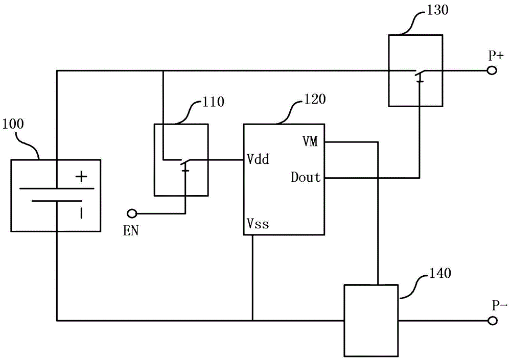
[0038]Aiming at the problem that the service life of the battery in the prior art is reduced or even damaged due to long-term storage, after analysis and testing by the inventor, it is found that the main reason is the weak power consumption accumulation of the battery protection circuit during the idle process of the battery. In order to solve this problem , this embodiment firstly provides a battery protection circuit. figure 2 It is a schematic block diagram of a battery protection circuit according to an embodiment of the present invention. As shown in the figure, the battery protection circuit generally includes a battery protection chip 120 and a chip control switch 110, wherein the battery protection chip 120 is used to provide the battery 100 with Various protection control signals (such as over-discharge protection signals and over-current protection signals), the battery protection chip 120 can be selected according to the voltage and power supply requirements of the...


PUM


Abstract

The invention discloses a battery protection circuit, an electric energy supply device and an electronic device. The battery protection circuit is externally connected with a battery and comprises a battery protection chip for providing protection control signals to the battery, and the battery protection chip at least comprises a positive chip power supply input pin. The battery protection circuit further comprises a chip control switch which is arranged between the positive chip power supply input pin and the positive electrode of the battery and configured as the connected or disconnected status in a controlled way; when the chip control switch is in the connected status, the positive chip power supply input pin of the battery protection chip is connected with the positive electrode of the battery, so that the battery protection chip begins to operate; when the chip control switch is in the disconnected status, the positive chip power supply input pin of the battery protection chip is disconnected with the positive electrode of the battery, so that the battery protection chip stops to operate. Through the solution, the battery is excessively discharged because the battery protection chip consumes power, the service life of the battery is prolonged.

Description

technical field [0001] The invention relates to the technical field of power supply protection, in particular to a battery protection circuit, a power supply device and an electronic device. Background technique [0002] Power supply is an important part of electronic equipment. Rechargeable batteries are one of the most widely used ones. At present, most mobile terminals such as smart phones and tablet computers use rechargeable batteries as power sources. [0003] The characteristics of rechargeable batteries, especially lithium-ion batteries, determine that they cannot be charged and discharged by overcharge, overdischarge, overcurrent, short circuit and ultra-high temperature. Therefore, rechargeable batteries generally need to be used with battery protection circuits. The protection circuit of the rechargeable battery is different because of the protection chip used and the power supply voltage of the battery. The circuit and parameters are different, but the protectio...

Claims


Application Information

Patent Timeline
Patent Type & Authority Applications(China)
IPC IPC(8): H02H7/18H02J7/00
CPCH02H7/18H02J7/00
Inventor 李东声
Owner TENDYRON CORP
Why Eureka
Try Eureka