Main unit cabinet of compact power supply cabinet, assembly method thereof, and component arrangement method in the cabinet

A main unit and unit cabinet technology, applied in the direction of electrical components, power electronics modification, output power conversion device, etc., can solve the problem of unreasonable device placement and space layout, large power cabinet, heat dissipation and maintenance, device installation, Inconvenient maintenance and other problems, to achieve the effect of expanding the installation application occasions, simple structure, and small footprint

Active Publication Date: 2017-02-15
CSR ZHUZHOU ELECTRIC LOCOMOTIVE RES INST
View PDF10 Cites 0 Cited by
  • Summary
  • Abstract
  • Description
  • Claims
  • Application Information

AI Technical Summary

Problems solved by technology

[0006] With the development of the industry, various forms and schemes have emerged in the design of power cabinets. At present, most of the existing power cabinets have problems with large size, heat dissipation and maintenance: some power cabinets have many components, and the unreasonable placement of components leads to The cabinets are large in size and low in power density; some devices are inconvenient to install and maintain due to unreasonable device placement and space layout, and interfere with each other; some have multiple air duct designs, but the structural design is complicated and the cost is high. Even the heat dissipation effect is not good; most of the power cabinets need to reserve a certain operating space and heat dissipation space around the power cabinet when they are used on site, which increases the cost of customers and limits the use of power cabinets

Method used


Image

  • Main unit cabinet of compact power supply cabinet, assembly method thereof, and component arrangement method in the cabinet
  • Main unit cabinet of compact power supply cabinet, assembly method thereof, and component arrangement method in the cabinet
  • Main unit cabinet of compact power supply cabinet, assembly method thereof, and component arrangement method in the cabinet

Examples


Embodiment 1

[0065] Embodiment 1: (a compact power cabinet including the first main unit cabinet 2)

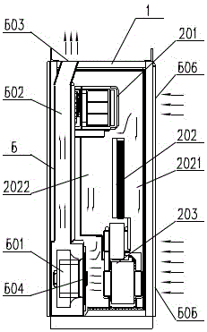
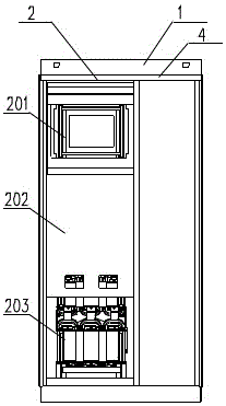
[0066] like Figure 1 to Figure 4As shown, a compact power supply cabinet includes a cabinet body 1, a first main unit cabinet 2 and an AC output unit cabinet 4 installed side by side in the cabinet body 1; the first main unit cabinet 2 includes a A power module unit 201, an electrical board 202 vertically installed in the middle, a magnetic component system 203 installed in the lower part, and a heat dissipation air duct system 5 installed in the rear area for multi-path cooling and heat dissipation; The AC output unit cabinet includes an AC output power distribution system, and the AC output power distribution system is connected to the first main unit cabinet 2 through bus bars or cables. The AC output power distribution system is mainly composed of a grid-connected contactor, a grid-connected circuit breaker, and an AC output terminal, and the connection between its internal component...

Embodiment 2

[0072] Embodiment 2: (compact power supply cabinet including the second main unit cabinet 3)

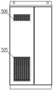
[0073] like Figure 5 to Figure 7 As shown, a compact power supply cabinet differs from the first embodiment in that the main unit cabinet is the second main unit cabinet 3, and the difference between the second main unit cabinet 3 and the first main unit cabinet 2 is: the second main unit cabinet There are two power module units 201 , magnetic component systems 203 and cooling air duct systems 5 in the unit cabinet, and the others are the same as those in the first embodiment.

[0074] The heat dissipation fan 501 in the heat dissipation air duct system 5 in the above technical solution can also be installed at the position of the air outlet 503 of the cabinet body; the mutual position of the main unit cabinet and the AC output unit cabinet can be changed, such as: stacked up and down.

[0075] Below in conjunction with the comparison with prior art, the specific scheme of the pres...


PUM


Abstract

The invention discloses a compact main unit cabinet of a power cabinet, an assembly method thereof and an arrangement method for components therein. The compact main unit cabinet of the power cabinet comprises a main unit cabinet body, a power module unit arranged at the upper part, an electric plate vertically arranged at the middle, a magnetic component system arranged at the lower part, and a cooling air passage system arranged at the rear region; the power module unit comprises an integrated radiator, a power switch apparatus, a direct current support capacitor and a control circuit board stacked in the front and back; the magnetic component system comprises more than two sub-components stacked in the vertical direction. The compact main unit cabinet of the power cabinet is convenient for placing components, the cooling performance is good, the cabinet volume is small, the compact arrangement for the components in the power cabinet and good cooling effect are effectively realized, and moreover, the structure is simple, and the manufacturing and mounting are easy to realize. The cabinet body has advantages that the operation and maintenance are performed from the front, a reliable wall / barrier is arranged at the back side, the cabinet body is compact, and the floor space is small.

Description

technical field [0001] The invention relates to the technical field of power electronic equipment. Background technique [0002] Power cabinet, as a power electronic conversion device, is an industrial achievement of the development of modern power electronics technology. It is generally equipped with power switching devices (IGBT, etc.), magnetic components (transformers, reactors, etc.) and power distribution components (switches, etc.) Components are widely used in many fields such as new energy (solar photovoltaic / wind power, etc.), power grid, etc. The high power density, stable working performance, and convenient operation and maintenance of high-power power supply cabinets are not only the needs of users, but also the goal of the industry. The power density, reliability and operation and maintenance of the power cabinet directly affect the market application competitiveness of the power cabinet, and whether the heat dissipation design and the system structure layout ...

Claims


Application Information

Patent Timeline
Patent Type & Authority Patents(China)
IPC IPC(8): H02M1/00H05K7/20
CPCH02M1/00H05K7/20909
Inventor 蹇芳管仁德唐海燕唐洲陈艺峰吴建雄张蓉刘玉柱廖远辉张洪浩
Owner CSR ZHUZHOU ELECTRIC LOCOMOTIVE RES INST
Why Eureka
Try Eureka