Method for controlling uniform heating of switch device of switch power source

A switching device and switching power supply technology, which is applied in the direction of electrical components, control/regulation systems, instruments, etc., can solve the problem of uneven heating of switching devices, and achieve the effect of prolonging life and uniform heating

Inactive Publication Date: 2015-05-06
SICHUAN INJET ELECTRIC CO LTD +1
View PDF4 Cites 98 Cited by
  • Summary
  • Abstract
  • Description
  • Claims
  • Application Information

AI Technical Summary

Problems solved by technology

[0007] The purpose of the present invention is to overcome the problem of uneven heating of each switching device in a switching power supply comprising multiple switching devices, and to provide a control method for uniform heating of switching devices in a switching power supply that can make each switching device generate heat evenly and effectively prolong the life of the switching device , the switching power supply includes a full-bridge converter, the switching device in the full-bridge converter is a switching tube, and the switching devic

Method used


Image

  • Method for controlling uniform heating of switch device of switch power source
  • Method for controlling uniform heating of switch device of switch power source
  • Method for controlling uniform heating of switch device of switch power source

Examples


Example Embodiment

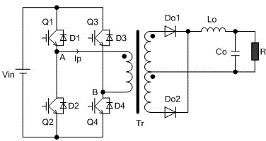
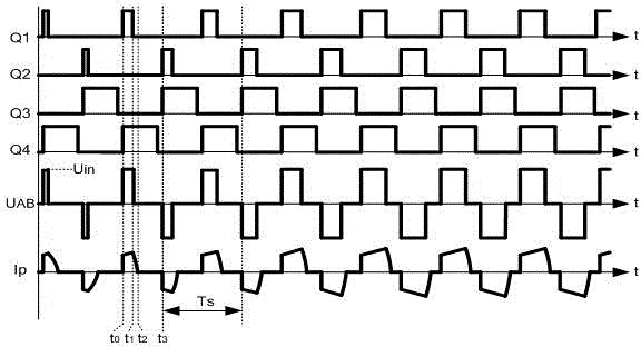
[0017] Embodiment 1: The purpose of this embodiment is to overcome the problem of uneven heating of each switching tube in a switching power supply including switching tubes, and to provide a method for controlling uniform heating of switching power supply switching tubes. The switching power supply includes a full-bridge converter, The structure of the full-bridge converter is figure 1 As shown, the four switching devices Q1 (first switching device), Q2 (second switching device), Q3 (third switching device), and Q4 (fourth switching device) in the full-bridge converter are all switching devices. , The switching device sequence (that is, the turn-on or turn-off sequence) of each switching device in the full-bridge converter is cycle alternately, that is, the switching device as the leading arm and the switching device as the lagging arm are cycled alternately, The alternating period Tp is twice the switching control period Ts of each switching device; that is, one alternating pe...

Example Embodiment

[0020] Example 2: Such as Figure 4 As shown, each switching device in the full-bridge converter is composed of two or more switching tubes in parallel, and the control pulses of the two or more switching tubes constituting each switching device are the same. That is, the switching tubes Q11~Q1n are connected in parallel to receive the same switching tube control pulse; Q21~Q2n are connected in parallel to receive the same switching tube control pulse; Q31~Q3n are connected in parallel to receive the same switching tube control pulse; Q41~Q4n are connected in parallel to receive the same switching tube control pulse. Switch tube control pulse; four groups of pulse signals can be pressed image 3 The control pulse generation method shown can realize parallel IGBTs.

Example Embodiment

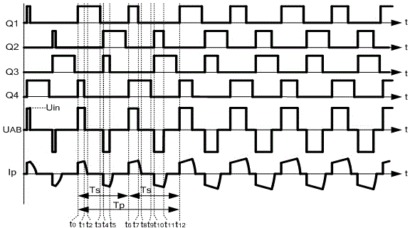
[0021] Embodiment 3: This embodiment provides a method for controlling uniform heat generation of a switching power supply switch tube. The switching power supply includes a full-bridge converter. The structure of the full-bridge converter is as follows figure 1 As shown, the four switching devices Q1 (first switching device), Q2 (second switching device), Q3 (third switching device), and Q4 (fourth switching device) in the full-bridge converter are all switching devices. In the full-bridge converter, the switching device as the leading arm and the switching device as the lagging arm alternate in cycles, and the alternating period Tp is 6 times the switching control period Ts of each switching element; that is, one alternating period Tp contains 6 switching control periods Ts. For example, in the first three switching control periods Ts in an alternating period Tp, Q1 and Q2 constitute a lagging arm, and Q3 and Q4 constitute a leading arm, then in the same alternate period Tp, th...


PUM


Abstract

The invention relates to the field of switch power source control, in particular to a method for controlling uniform heating of switch devices of a switch power source. The switch power source comprises a full bridge converter, the switch devices in the full bridge converter are switch tubes, the sequence of the switch devices in the full bridge converter alternately changes periodically, and the alternating period is N times of the switch control period of the switch devices, wherein N refers to a natural number larger than 2. Alternate soft turnoff of the switch devices is realized by alternately changing turnoff sequence of the switch devices composed of the switch tubes of the full bridge converter in the switch power source, so that the switch devices are uniform in heating within a long time period, and service life of the whole switch power source is prolonged.

Description

technical field [0001] The invention relates to the field of switching power supply control, in particular to a control method for uniform heating of switching devices of the switching power supply. Background technique [0002] With the development of industrial technology, the power supply has transitioned from the traditional thyristor power supply to switching power supply, and the application of switching power supply is becoming more and more extensive. There are many methods for DC converters in switching power supplies. In high input voltage or medium and high power converters, full bridge converters are often used. With the traditional hard switching technology, there are power switching tubes (such as IGBT, etc.) with large switching stress, large switching device losses, and low conversion efficiency. Especially for high-power power supplies for industrial applications, high power loss has a great impact on production costs, and high energy consumption also cause...

Claims


Application Information

Patent Timeline
IPC IPC(8): H02M3/335
CPCH02M3/335
Inventor 杜辉邓长春邓永华张联学
Owner SICHUAN INJET ELECTRIC CO LTD
Why Eureka
Try Eureka