Punching die

A technology of stamping dies and dies, applied in the field of dies, can solve problems such as worker fatigue, reduce die life, and large vibration of punching machines, and achieve the effects of less vibration of machine tools, prolonging service life, and reducing manpower and material resources

Inactive Publication Date: 2015-05-13
LIUZHOU SHUNLING AUTO PARTS
View PDF6 Cites 1 Cited by
  • Summary
  • Abstract
  • Description
  • Claims
  • Application Information

AI Technical Summary

Problems solved by technology

[0004] At present, most stamping dies are a kind of die that directly breaks the material, including a die and a punch. The upper end of the die is a product placement platform. Since all positions of the upper end surface of the die of the existing mold are at the same level, all the parts to be punched on the material are stressed at the same time during stamping, so that the tonnage of the punching machine is too large, and the vibration of the punching machine is too large , the noise is large, which seriously affects the hearing of the workers, is not good for the health of the workers, and can easily lead to the fatigue of the workers
In addition, the mold vibrates too much and has abnormal noise, which is easy to cause the punch and die to be bitten and damaged, which reduces the life of the mold

Method used


Image

  • Punching die
  • Punching die

Examples


Embodiment Construction

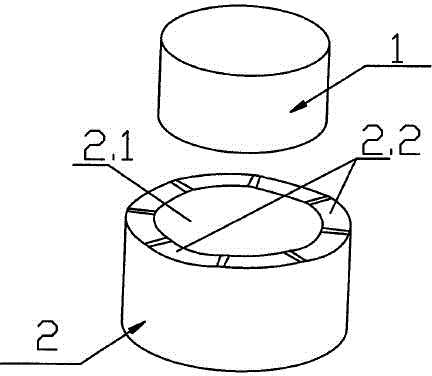
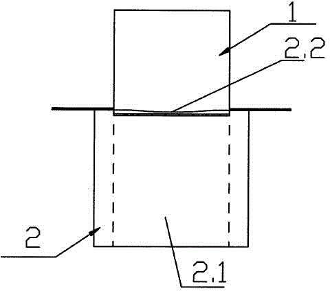
[0015] Such as figure 1 , 2 As shown, the present invention discloses a stamping die, including a punch 1 and a die 2, the die 2 is cylindrical, the inner cavity of the die 2 is the stroke cavity 2.1 of the punch 1, the punch 1 and the die 2 The shape and size of the inner cavity match, the upper end surface of the die 2 is a raw material placement platform, the upper end surface of the die 2 is provided with a feeding mechanism, and the feeding mechanism is set horizontally with the placement platform, and the shear surface at the upper end surface of the die 2 is 2.2 into a curved shape.

[0016] The longitudinal section of the shearing surface 2.2 is corrugated. The shearing surface of the die on the existing stamping die is a plane. After the material is placed on it, when stamping, all surfaces of the material are stressed, please punch it off at the same time, so the requirements for the punching machine are high. And the shearing surface 2.2 of the present invention ...


PUM


Abstract

The invention provides a punching die. The punching die comprises a male die and a female die. The female die is in a cylinder shape. An inner cavity of the female die is a punch travel cavity. The size of the male die is matched with the size of the inner cavity of the female die. The upper end face of the female die is provided with a raw material containing table. A feed mechanism is arranged on the side face of the upper end face of the female die. The feed mechanism and the containing table are horizontally arranged. A shearing face of the containing table on the upper end face of the female die is in a bent face shape. The punching die further comprises a sliding mechanism which is detachably connected with the bottom of the female die. The punching die has the advantages that shearing cotton yarn of the female die is designed into the bent face shape, the aims of conducting material force bearing step by step and conducting punching part by part are achieved, and the requirement for greatly reducing the machine tool tonnage is achieved; cost is saved, the machine tool vibration is not large, and noise is reduced; the die vibration is small, no abnormal sound is generated, the service life of the male die and the female die is prolonged, the quality of the die is improved, and manpower and material resources are reduced.

Description

technical field [0001] The invention relates to the field of molds, in particular to stamping molds. Background technique [0002] Stamping die is a special process equipment for processing materials (metal or non-metal) into parts (or semi-finished products) in cold stamping processing, called cold stamping die (commonly known as cold stamping die). Stamping is a pressure processing method that uses a mold installed on a press to apply pressure to the material at room temperature to cause separation or plastic deformation to obtain the required parts. [0003] Stamping die is an indispensable process equipment for stamping production, and it is a technology-intensive product. The quality, production efficiency and production cost of stamping parts are directly related to the design and manufacture of molds. [0004] At present, most stamping dies are a kind of die that directly breaks the material, including a die and a punch. The upper end of the die is a product placeme...

Claims


Application Information

Patent Timeline
Patent Type & Authority Applications(China)
IPC IPC(8): B21D28/14
CPCB21D28/14
Inventor 周云
Owner LIUZHOU SHUNLING AUTO PARTS
Why Eureka
Try Eureka