Automatic mechanical arm

A robotic arm, robotic arm technology, applied in the direction of automatic in/out of workpieces, metal processing mechanical parts, grinding feed motion, etc., can solve the problems of high operator requirements, safety accidents, and high costs, achieving high efficiency and reducing The effect of personnel injury accidents

Active Publication Date: 2015-05-13
SHENZHEN KING TEAM PRECISION TECH
View PDF9 Cites 10 Cited by
  • Summary
  • Abstract
  • Description
  • Claims
  • Application Information

AI Technical Summary

Problems solved by technology

This traditional manual work method has high requirements for operators, and the effici

Method used


Image

  • Automatic mechanical arm
  • Automatic mechanical arm
  • Automatic mechanical arm

Examples


Embodiment Construction

[0018] In order to make the purpose, technical solutions and advantages of the embodiments of the present invention clearer, the technical solutions in the embodiments of the present invention will be clearly described below in conjunction with the accompanying drawings in the embodiments of the present invention. Obviously, the described embodiments are the Some, but not all, embodiments are invented. Based on the embodiments of the present invention, all other embodiments obtained by persons of ordinary skill in the art without making creative efforts belong to the protection scope of the present invention.

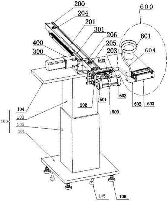
[0019] A kind of automatic mechanical arm (hereinafter referred to as mechanical arm), such as figure 1 As shown, including frame 100, frame 100 among the present invention is made up of four parts, is respectively base 101, lifting base 102, lifting column 103 and work master table 104, wherein, lifting base 102 is fixed on the base 101, and the lifting The column 103...


PUM


Abstract

The invention belongs to the technical field of mechanical arm, and relates to an automatic mechanical arm specifically. The automatic mechanical arm comprises a rack (100), a servo motor (300) is arranged on the rack (100), a mechanical arm (200) is arranged on the rack (100), and the mechanical arm (200) conducts concertina movement driven by the servo motor (300). A fixture holder (500) is arranged at the end of the mechanical arm (200), and a feeding fixture (501) and a reclaiming fixture (502) are arranged on the fixture holder (500). A first cylinder (202) and a second cylinder (203) are arranged on the mechanical arm (200), the first cylinder (202) is used for controlling the rotation of the fixture holder (500), and the second cylinder (203) is used for controlling the horizontal moving of the fixture holder (500). The fixture holder of the mechanical arm can rotate driven by the cylinder, and the translocation of an intermittence between the feeding fixture and the reclaiming fixture is controlled correspondingly, perform bodied that needs processing and the processed elements are clamped respectively, the corresponding processing is conducted, the automatic material clamping, the feeding and reclaiming are achieved, and manual labor is replaced greatly.

Description

technical field [0001] The invention relates to the field of mechanical arms, and more specifically relates to an automatic mechanical arm. Background technique [0002] The robotic arm is currently the most widely used automated mechanical device in the field of robotics. It can be seen in industrial manufacturing, medical treatment, entertainment services, military, semiconductor manufacturing, and space exploration. Although their shapes are different, they all have a common feature, that is, they can accept instructions and precisely locate a certain point in three-dimensional (or two-dimensional) space for operation. For the field of mechanical processing, due to the relatively large differences in the structures of lathes, machining centers, grinders, and planers, and the mechanical arm is limited by its own structure, the application of mechanical arms in the field of machining is very immature. Therefore, the existing The technologies are all special feeding equipme...

Claims


Application Information

Patent Timeline
IPC IPC(8): B23Q7/04B24B41/00
CPCB23Q7/04B24B41/00B23Q2707/02B24B41/005
Inventor 吴春谅林卫波戚青涛胡刚
Owner SHENZHEN KING TEAM PRECISION TECH
Why Eureka
Try Eureka