Hybrid electric vehicle, gear-shifting control method thereof and power transmission system thereof

A hybrid electric vehicle and power transmission system technology, applied in the field of vehicles, can solve problems such as low economy, lack of modes, and inability to realize different modes of drive requirements, and achieve the effect of improving ride comfort and comfort, and wide application range

Active Publication Date: 2015-05-13
BYD CO LTD
View PDF5 Cites 53 Cited by
  • Summary
  • Abstract
  • Description
  • Claims
  • Application Information

AI Technical Summary

Problems solved by technology

[0003] The above-mentioned shift control method has the following disadvantages: (1) only considers the speed regulation process of upshifting and downshifting, in fact, the speed regulation still has the situation of downshifting and shifting when the whole vehicle is running; (2) lack of modes (for example, pure Electric mode, hybrid mode) switch, the control mode is single, the driving requirements of different modes cannot be realized, and the economy is also low

Method used


Image

  • Hybrid electric vehicle, gear-shifting control method thereof and power transmission system thereof
  • Hybrid electric vehicle, gear-shifting control method thereof and power transmission system thereof
  • Hybrid electric vehicle, gear-shifting control method thereof and power transmission system thereof

Examples


Embodiment 1

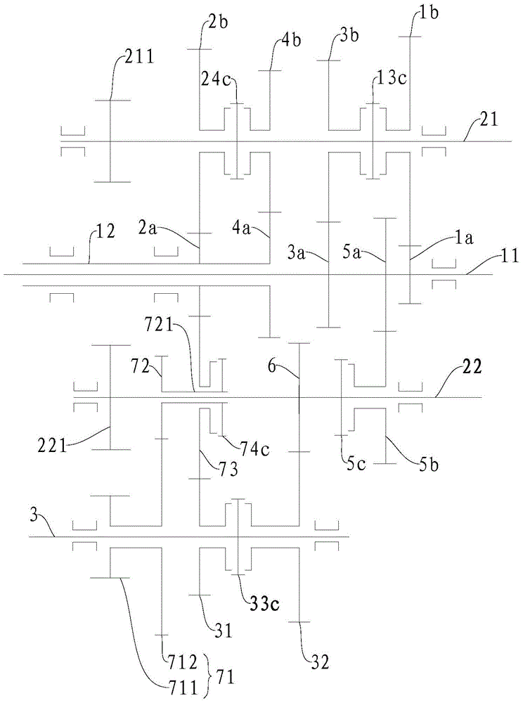
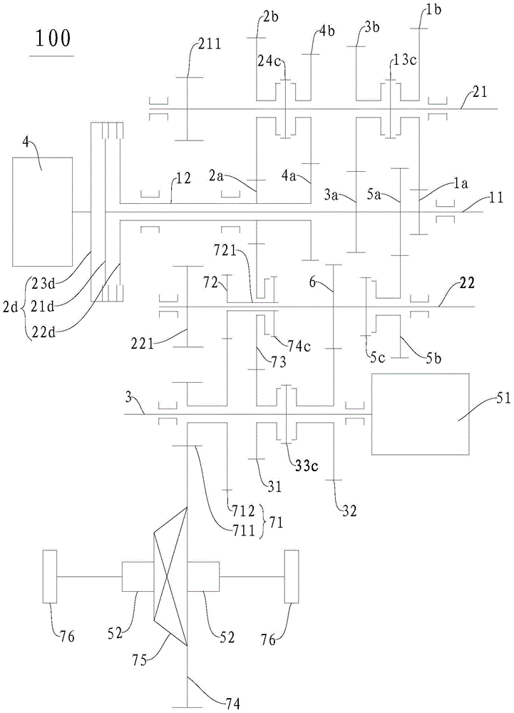
[0112] Such as figure 2 As shown, the engine 4 is connected with the input end 23d of the double clutch 2d, the first output end 21d of the double clutch 2d is connected with the first input shaft 11, the second output end 22d of the double clutch 2d is connected with the second input shaft 12, and the double clutch 2d is connected with the second input shaft 12. The input end 23d of the clutch 2d and the first output end 21d and the second output end 22d of the double clutch 2d can be in disconnected state at the same time, or the input end 23d of the double clutch 2d can be connected with the first output end 21d and the second output end 21d of the double clutch 2d. One of the two output terminals 22d is engaged, or the input terminal 23d of the dual clutch 2d can be simultaneously engaged with the first output terminal 21d and the second output terminal 22d of the dual clutch 2d.

[0113] The second input shaft 12 is a hollow shaft structure, the first input shaft 11 is a...

Embodiment 2

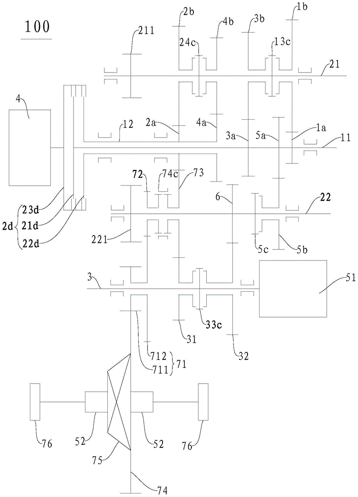
[0174] Such as image 3 As shown, the power transmission system 100 in this embodiment and figure 2 The main differences of the drivetrain 100 shown in are at the reverse intermediate gear 72, the idler intermediate gear 73 and the reverse synchronizer 74c. In this embodiment, the reverse intermediate gear 72 and the intermediate idler gear 73 are adjacent to the second output shaft 22, and the reverse synchronizer 74c is disposed on the intermediate idler gear 73 and is used to engage the reverse intermediate gear. 72. For the rest it can be used with figure 2 The power transmission system 100 in the embodiment is basically the same, and will not be repeated here.

Embodiment 3

[0176] Such as Figure 4 As shown, the power transmission system 100 in this embodiment and image 3 The main difference in the drivetrain 100 shown in is the configuration of the intermediate idler 73 . In this embodiment, the intermediate idler gear 73 is configured as a double gear, and has gear portions 731, 732, one of which gear portion 731 meshes with the second gear driving gear (that is, with the gear driving gear on the one of the input shafts). ), the other gear portion 732 meshes with the first gear 31 of the motor power shaft. For the rest it can be used with image 3 The power transmission system 100 in the embodiment is basically the same, and will not be repeated here.

[0177] In addition, embodiments according to the present invention further provide a vehicle including the power transmission system 100 as described above. It should be understood that other components of the vehicle according to the embodiments of the present invention, such as the drivin...


PUM


Abstract

The invention discloses a gear-shifting control method of a hybrid electric vehicle. The gear-shifting control method comprises the following steps of detecting operating parameters of the hybrid electric vehicle, judging the working modes of the hybrid electric vehicle, and carrying out speed governing gear-shifting control over a first electric motor generator according to the current working mode of the hybrid electric vehicle and the operating parameters of the hybrid electric vehicle so that the hybrid electric vehicle can achieve gear-shifting control, wherein the operating parameters of the hybrid electric vehicle comprise the speed, the accelerator pedal signals and the current gear of the hybrid electric vehicle, and the working modes comprise the pure electric mode and the hybrid power mode. According to the method, speed governing gear-shifting of motors in various working conditions is taken into consideration, the smoothness and the comfort of the whole vehicle are improved, and the application range is expanded. The invention further discloses a power transmission system and the hybrid electric vehicle.

Description

technical field [0001] The invention relates to the technical field of vehicles, in particular to a shift control method of a hybrid electric vehicle, a power transmission system of the hybrid electric vehicle and the hybrid electric vehicle. Background technique [0002] Propose a kind of shift control method of the hybrid electric vehicle with AMT gearbox in the related art, comprise the following steps: A: HCU (Hybrid Control Unit, hybrid controller) judges whether to receive TCU (Transmission Control Unit, gearbox controller); B: When the HCU receives the shift signal from the TCU, the HCU simultaneously sends an instruction to the motor and the engine to reduce the torque to zero; C: When the torque of the motor and the engine are both reduced to zero , the TCU controls the synchronizer to move to the neutral position; D: When the TCU controls the synchronizer to move to the neutral position, the HCU sends an instruction to the motor to generate reverse torque for speed...

Claims


Application Information

Patent Timeline
Patent Type & Authority Applications(China)
IPC IPC(8): B60W10/08B60W20/00B60W40/00B60W40/105B60K17/12B60K6/22B60W20/20B60W20/30B60W20/40
CPCB60K6/36B60W10/08B60W10/11B60W20/30B60W30/19B60W2520/10B60W2540/10B60W2540/16B60K6/547B60W10/06B60W10/113B60W2050/0011B60W2510/081B60W2510/1005B60W2710/081B60W2710/083B60W2710/1005B60W2720/10B60W2720/106B60W20/40B60W20/20B60K2006/4808Y10S903/902Y02T10/62B60W10/10B60W2510/10B60W2520/105B60W2710/0644B60W2710/10
Inventor 杨冬生廉玉波张金涛罗红斌
Owner BYD CO LTD
Why Eureka
Try Eureka