[0018] The present invention will be further described below with reference to the drawings and embodiments, but the protection scope of the invention is not limited by the embodiments.
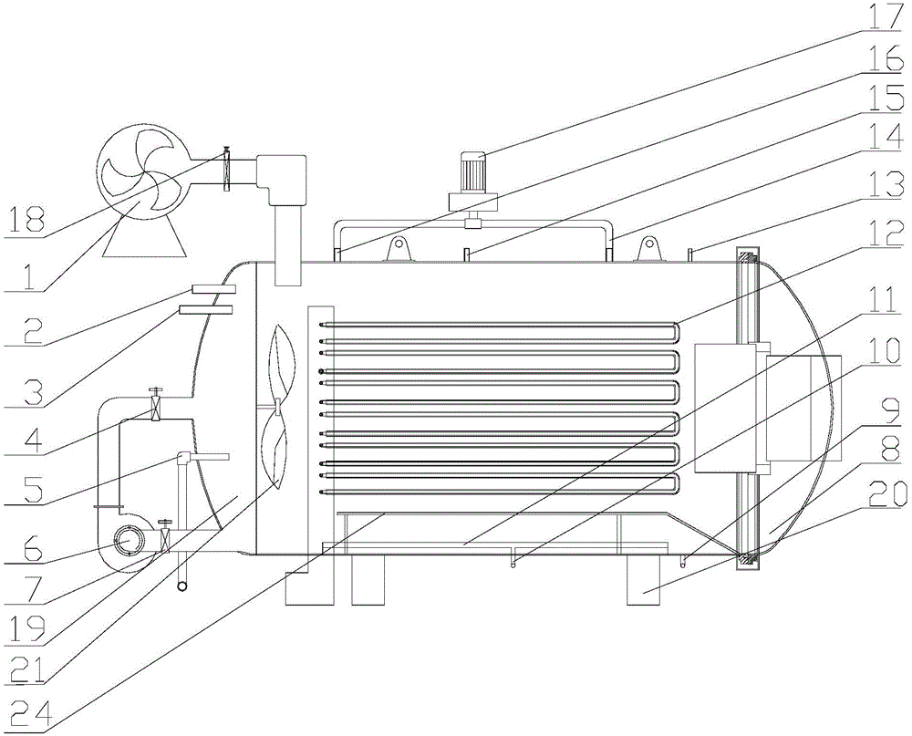
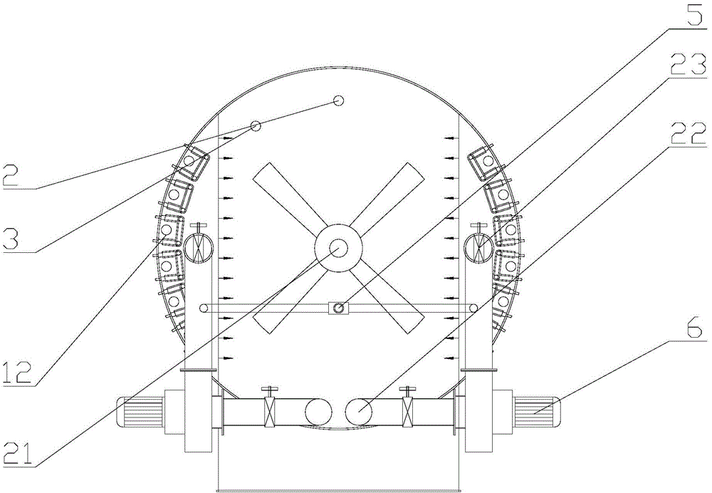
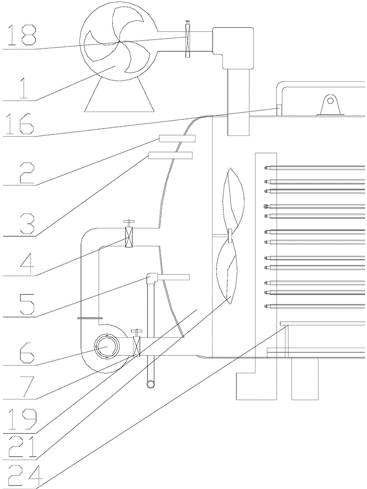
[0019] see figure 1 , figure 2 , image 3 , Figure 4 As shown, a textile shaping and drying integrated machine is mainly composed of a base 20, a body 19, and a sealed door 8. It also includes an electric heating tube 12, a vacuum pump 1, a dehumidification fan 17, a circulating fan 6, a magnetic automatic fan 21, and a high-pressure spray Sprinkler pipe 5, safety valve 15, exhaust gas supplement valve 9, steam plate 11 and steam interface 10; the body 19 is made of steel plate and is shaped like a barrel. The front side of the body 19 is provided with a sealed door that fits the body 19 8. The airtight door 8 and the body 19 are connected by hinges; the inside of the body 19 is provided with electric heating tubes 12, which are arranged in two rows, which are arranged symmetrically along the inner sides of the body 19; on the outside of the body 19, there is one The vacuum pump 1, which is connected to the inside of the body 19 through a pipe, is also provided with a vacuum pump throttle valve 18 on the pipe between the vacuum pump 1 and the body 19; on the upper part of the body 19, there is a dehumidification fan 17, a dehumidification fan 17 There are two metal ducts connected to the inside of the body 19, and the metal ducts are respectively provided with a dehumidification fan throttle valve I14 and a dehumidification fan throttle valve II16; on the left and right sides of the outer rear end of the body 19, a circulating fan 6 The circulating fan 6 is provided with a circulating fan suction pipe 22 and a circulating fan blowing pipe 23. The circulating fan suction pipe 22 passes through the body 19 and connects to the inside of the body 19, located at the bottom end of the body 19, and the circulating fan blowing pipe 23 passes through The body 19 is connected to the inside of the body 19 and is located behind the electric heating pipe 12 inside the body 19; the circulating fan suction pipe 22 is provided with a circulating fan suction throttle valve 7, and the circulating fan blowing pipe 23 is provided with a circulating fan blowing section Flow valve 4; between the circulating fan blowing pipe 23 and the electric heating tube 12, there is also a magnetic automatic fan 21, which is fixedly installed inside the body 19 and behind the electric heating tube 12 through a bearing; Between the automatic fan 21 and the circulating fan blowing pipe 23, there is also a high-pressure spray water pipe 5. The high-pressure spray water pipe 5 is in the shape of a horizontal strip. A spray nozzle is provided on the side facing the electric heating pipe 12. The spray nozzle will spray The output water is atomized; below the electric heating pipe 12, there is a steam plate 11 with a plurality of small holes on the steam plate 11; the bottom of the steam plate 11 is provided with a steam interface 10 that opens to the outside of the outer body 19, The steam circulates into the steam plate 11 through a pipe connected to the steam interface 10; between the steam plate 11 and the heating pipe 12, a pair of rails 24 are provided for the trolley for loading materials.
[0020] On the top of the body 19, there is a safety valve 15. When the pressure inside the equipment exceeds the limit pressure, the safety valve 15 will automatically open to relieve the pressure; at the bottom of the body 19, there is an exhaust and supplementary air valve 9. When the pressure is drawn by the dehumidifier fan 17 to a slightly negative pressure state, the exhaust gas supplement valve 9 opens for gas supplement. When the internal pressure of the device is too high, the exhaust gas supplement valve 9 opens for exhaust gas.
[0021] On the body 19, there are also a temperature sensor 2, a humidity sensor 3 and a pressure gauge 13. The temperature sensor 2 is used to detect the working temperature inside the body, the humidity sensor 3 is used to detect the working humidity inside the body, and the pressure gauge 13 is used to detect The working pressure inside the equipment reflects the pressure inside the body 19 in digital form.
[0022] When working, the operator pushes the trolley loaded with materials to the inside of the machine body 19 along the rail 24, closes the sealed door 8, locks the sealed door 8 and starts the equipment.
[0023] Shaping work: the airtight door 8 is sealed and the magnetic automatic fan 21 starts blowing. The vacuum pump 1 starts to draw out the air inside the body 19, so that the inside of the body 19 is in a negative pressure state; when the inside of the body 19 reaches the state of negative pressure setting, the vacuum pump section The flow valve 18 is closed; the electric heating pipe 12 is energized to start heating to the set temperature, and the steam is delivered to the steam plate 11 through the steam interface 10, and the small holes on the steam plate 11 diffuse the steam into the body 19, and at the same time, the electric heating on both sides The heating pipe 12 continues to work to ensure the temperature rise rate in the body 19; when the humidity sensor 3 detects that the working humidity inside the body is insufficient, the high-pressure spray water pipe 5 works, spraying atomized water to the electric heating pipes 12 on both sides to compensate Humidity inside the body 19; the steam is continuously heated by the electric heating tube 12 to enhance the penetration of the material, realize the required temperature and humidity setting conditions of the material, and finally achieve the purpose of finalizing the material.
[0024] Drying work: After the material is finalized, the steam interface 10 stops supplying steam, the electric heating pipe 12 and the magnetic automatic fan 21 continue to work; at the same time, the dehumidification fan 17 starts, the dehumidification fan throttle valve I14 and the dehumidification fan throttle valve II16 Turn on at the same time to take away the steam and moisture inside the body 19, and the exhaust gas supplement valve 9 is opened to compensate for the air drawn by the dehumidification fan 17; the temperature sensor 2 detects whether the temperature inside the body 19 reaches the setting of the drying material At the same time, the circulation fan 6 starts to work, and the circulation fan suction pipe throttle valve 7 and the circulation fan blowing pipe throttle valve 4 are opened, so that the hot air inside the body 19 circulates, so that the material receives the hot air more evenly. Play the drying effect, until the drying reaches a certain humidity value, the drying process is completed, and the whole process ends.
[0025] The specific embodiments of the present invention have been described above. It should be understood that the present invention is not limited to the above specific embodiments, and those skilled in the art can make various deformations or modifications within the scope of the claims, which does not affect the essence of the present invention.