Oil-water separator

An oil-water separation device and a technology for residual oil, which are used in general water supply conservation, water conservancy projects, and open-air water surface cleaning, etc., and can solve problems such as the inability to quickly recover small river channels.

Active Publication Date: 2015-05-13
PIPECHINA SOUTH CHINA CO
View PDF5 Cites 2 Cited by
  • Summary
  • Abstract
  • Description
  • Claims
  • Application Information

AI Technical Summary

Problems solved by technology

[0003] Aiming at the problems existing in the prior art, the embodiment of the present invention provides an oil-water separation device, which is used to solve the technical problem in the prior art that oil spills in small rivers cannot be quickly recovered

Method used


Image

  • Oil-water separator
  • Oil-water separator

Examples


Embodiment 1

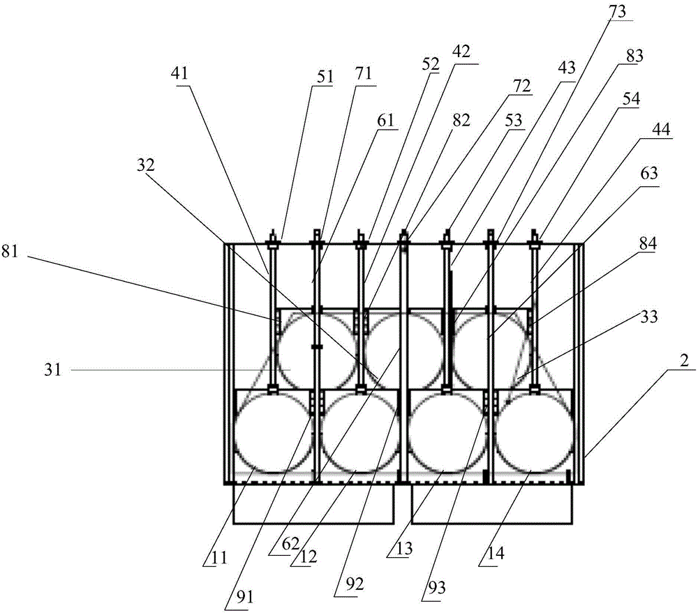
[0029] This embodiment provides an oil-water separation device, such as figure 1 As shown, the device includes: a first group of rams 1, a frame 2, a second group of rams 3, a first group of lead screws 4, and a second group of lead screws 5; wherein,

[0030] One end of the first group of gates 1 is arranged on the upper end of one side of the frame 2, and one side of the first group of gates 1 is attached to the first group of sealing grooves; the first group of gates 1 at least includes: The first gate plate 11, the second gate plate 12, the third gate plate 13 and the fourth gate plate 14; the first set of sealing grooves at least include: the first sealing groove, the second sealing groove, the third sealing groove and the first sealing groove Four sealing grooves.

[0031] The second group of rams 3 is arranged above the first group of rams 1, and one side of the second group of rams 3 is attached to the second group of sealing grooves; the second group of rams at least...

Embodiment 2

[0053] In practical application, when using the oil-water separation device provided by the present invention to carry out residual oil recovery in small rivers, the main steps are as follows:

[0054] 1) Site selection.

[0055] The water volume of small rivers has the characteristics of obvious seasonal changes, and the width of the river bed is different. Therefore, when choosing the location of the oil-water separation device, three factors should be considered: the width of the river bed, the height of the water level, and the velocity of the water flow. For example, for seasonal rivers, during the flood season, the water level is high and the flow velocity is fast. When selecting a location, avoid areas with high water level and high flow velocity, and choose locations with low flow velocity and low water level to facilitate device assembly and later oil-water separation. operate. When the river is in the dry season, you should choose a section with a relatively flat ri...

Embodiment 3

[0063] Utilize the oil-water separation device provided by the present invention, in the emergency drill of leaking oil spilled into the river held in a small river basin, 5 oil product interception points were set in combination with the channel width of the river and upstream tributaries and the river water flow conditions; At 3.9 kilometers from the point, the water velocity is about 0.2m / s, and the flow rate is 1m 3 / s, the width of the river bed is about 6 meters, combined with the situation of the river on site, the oil-water separation device and the earth dam shall be combined to implement the interception and recovery of oil products.

[0064] When an emergency occurs when oil spills into the ditch, the emergency repair personnel choose the river where the river bed is narrow and the river water flow is small, and the construction vehicles can easily enter the river, and place the oil-water separation device on the bank to prepare for equipment installation. The excav...


PUM


Abstract

The invention provides an oil-water separator. According to the oil-water separator, one end of a first gate segment set is arranged at the upper end of one side of a frame, and one side of the first gate segment set is attached to a first seal groove set. A second gate segment set is arranged above the first gate segment set, and one side of the second gate segment set is attached to a second seal groove set. One end of a first lead screw set is connected with the other end of the first gate segment set, and the other end of the first lead screw set is connected with a first nut set. One end of a second lead screw set is connected with one end of the second gate segment set, and the other end of the second lead screw set is connected with a second nut set. One end of a first flow guiding tube set is connected with the other side of the first gate segment set, and one end of a second flow guiding tube set is connected with the other side of the second gate segment set. The opening state of the first gate segment set and the opening state of the second gate segment set are controlled through the first nut set and the second nut set so that water can flow into the first flow guiding tube set or the second flow guiding tube set, and the water level can be regulated. Leaked oil is stopped at the positions above the first gate segment set and the second gate segment set, and the residual oil is rapidly recycled.

Description

technical field [0001] The invention relates to the technical field of petroleum engineering machinery, in particular to an oil-water separation device. Background technique [0002] With the rapid development and construction of long-distance pipelines in my country, the total mileage of underground oil pipelines has increased significantly, and the routes pass through complex areas, and intersections with rivers and ditches are very common. In terms of emergency response to oil spills into rivers, although a lot of research has been done on oil containment and oil recovery technologies at home and abroad, these studies are mainly aimed at the spread of oil spills in large waters such as oceans and rivers with wide water surfaces and stable water flow. Containment and recovery treatment, there is still a lack of corresponding research and new practical equipment on how to control the spread of oil spills in small rivers with narrow channels and small water volumes that cann...

Claims


Application Information

Patent Timeline
Patent Type & Authority Applications(China)
IPC IPC(8): E02B15/10
CPCY02A20/204E02B15/045
Inventor 张永盛孙雷刘志刚杨忠刘少柱张晓春李景昌郑国民祖宏波任帅民郝鹏亮王禹钦魏宝刚
Owner PIPECHINA SOUTH CHINA CO
Why Eureka
Try Eureka