Mine grouting technology and device with slurry stopping in hole

A grouting device and grouting technology, applied in mining equipment, shaft equipment, shaft lining, etc., can solve the problems of reducing dilution, segregation, large consumption of slurring pipes, and increasing the workload of sweeping holes, saving sweeping Hole time, improve grouting efficiency and effect, and reduce the difficulty of hole sweeping

Inactive Publication Date: 2015-05-13
HUBEI CENT SOUTH EXPLORATION & FOUND ENG
View PDF4 Cites 7 Cited by
  • Summary
  • Abstract
  • Description
  • Claims
  • Application Information

AI Technical Summary

Problems solved by technology

[0005] The whole hole filling of the lower shot pipe is to drill the borehole to the predetermined depth according to the design requirements, and after the borehole is washed clean, the shot pipe is lowered into the injection section. The shot pipe is generally made of steel pipe or plastic pipe. The high-pressure grouting sealer installed at the orifice is connected, and the grout is sent to the inlet of the borehole orifice sealer through the grouting pump and the grouting pipeline. The grout enters the injection section directly along the grouting pipe. The advantage of this method is that the grout enters directly In the injection section, the dilution and segregation of the grout by groundwater can be reduced. However, when grouting with this method, due to the development of karst fissures in the mine, the grout consumption is relatively large. Intermittent grouting is often used, that is, a certain amount of grouting is injected for a period of time , after sweeping the hole and then pouring, the grouting pipe must be replaced every time grouting, and the consumption of the grouting pipe is large; because the grouting pipe remains in the drilled hole, it increases the difficulty of hole sweeping; for the non-injected section above the top of the injected section, It also needs to scan the hole repeatedly, which greatly increases the workload of the hole scan

Method used


Image

  • Mine grouting technology and device with slurry stopping in hole

Examples


Embodiment Construction

[0034] The present invention will be further described in detail below through specific embodiments in conjunction with the accompanying drawings.

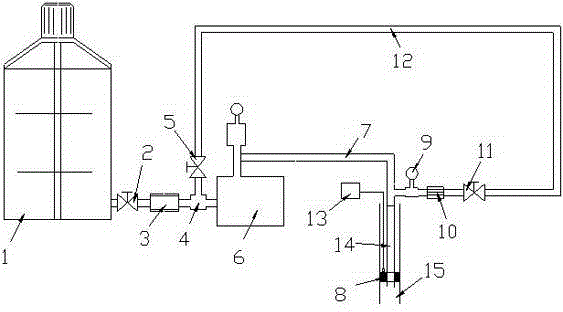
[0035] Please refer to figure 1 , the mine grouting process of stopping the grouting in the hole of the embodiment of the present invention, the process adopts the progressive mode to carry out segmental drilling and grouting from top to bottom, and the drilling and grouting of the last injection section are completed and wait for solidification, After the hole is swept, the drilling and grouting of the next injection section will be carried out until the preset drilling depth is reached, and finally the drilling hole will be sealed with thick slurry. Among them, the drilling and grouting of each injection section include the following step:

[0036]Step a), Drill the hole to the predetermined hole depth according to the design requirements. After confirming that the core in the hole is clean, lower the drill pipe and drilling to...


PUM


Abstract

The invention relates to the field of mine grouting, in particular to a mine grouting technology and device with slurry stopping in a hole. According to the technology, an advanced mode is adopted for performing segmented drilling and grouting from top to bottom, after drilling and grouting of a previous segment subjected to grouting end, the previous segment waits for congealing and hole sweeping is performed, operation is performed on a next segment subjected to grouting till a preset drilling depth is achieved, and finally, the drilled hole is sealed through thick slurry; the drilling and the grouting of each segment subjected to grouting include the steps that a, after the hole is drilled and washed, a pump-in test is performed, and the matching proportion of grouting slurry is selected according to a pump-in test result; b, slurry jetting pipes are connected with slurry stopping plugs, then, the slurry jetting pipes are connected to a hole opening one by one till the slurry stopping plugs are lowered to the tops of the segments subjected to grouting, the slurry stopping plugs expand, then, the slurry jetting pipe on the hole opening is sequentially connected with a slurry feeding pipe, a grouting pump, a flow meter and a secondary stirring barrel, a slurry detector is lowered to the upper portions of the slurry stopping plugs, and intermittent grouting is performed. The mine grouting technology and device are high in grouting efficiency and suitable for grouting of holes in different hole depths.

Description

technical field [0001] The invention relates to the field of mine grouting, in particular to a mine grouting process and device for stopping grout in holes. Background technique [0002] my country currently has more than 100,000 mines, many of which are basically completed due to the mining of shallow ore bodies, and the mining depth is developing in depth. Large, there is a major safety hazard of water inrush and flooding of the well. On July 17, 2001, a serious flooding accident occurred in Lajiapo Mine, Nandan County, Guangxi, killing 81 miners. On March 28, 2010, 38 miners were killed in a water flooding accident at the Wangjialing Coal Mine in Shanxi Province. Severe flooding directly leads to low recovery rate of ore bodies, resulting in a large waste of mineral resources. At the same time, a large amount of pumping and drainage of groundwater leads to a great waste of groundwater resources, and even serious environmental and geological problems such as ground subsid...

Claims


Application Information

Patent Timeline
Patent Type & Authority Applications(China)
IPC IPC(8): E21D11/10
CPCE21D11/10
Inventor 王伏春
Owner HUBEI CENT SOUTH EXPLORATION & FOUND ENG
Why Eureka
Try Eureka