
Coal-mass gas extraction method and device

A technology for gas extraction and coal body, which is applied in the field of coal body gas extraction device and coal body gas extraction, can solve the problems of not being able to guarantee the safe production of coal mines in a short time, not being able to use effectively, and wasting good resources, etc. To achieve the effect of shortening the extraction time, reducing the impact and making full use of it

Inactive Publication Date: 2015-05-13
张丽军
View PDF8 Cites 5 Cited by
  • Summary
  • Abstract
  • Description
  • Claims
  • Application Information

AI Technical Summary

Problems solved by technology

In the process of gas drainage in high-gas mines, due to factors such as equipment, technology, and personnel operations, the pipeline that generates negative pressure is only extended to the vicinity of the hole of the drainage borehole, and the coal mass cannot be drained to the greatest extent. Even if a part of the gas is extracted, the concentration of the gas is low and the drainage time is long, and it is also easily affected by the collapse of the coal body, which leads to the blockage of the drill hole, which not only cannot guarantee the safe production of the coal mine in a short time , the extracted gas should have a low concentration and cannot be effectively used. In most cases, it can only be discharged empty, which not only wastes high-quality resources, but also pollutes the environment and causes the greenhouse effect.

Method used


Image

  • Coal-mass gas extraction method and device
  • Coal-mass gas extraction method and device

Examples


Embodiment 1

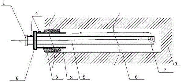
[0020] Such as figure 1 As shown, a coal gas drainage method is used for coal that is not easily broken. A drainage pipe 5 is laid from the orifice of the drainage borehole 6 to the bottom of the hole. The front end of the drainage pipe 5 is connected with the hole sealing device, and the end is set The secondary drainage hole 7 is drained by the negative pressure source pipe 1 of the mine drainage system connected to the plugging device, so that the gas in the drainage borehole flows to the bottom of the drainage borehole 6 from the secondary drainage hole 7 Into the drainage pipe 5.

[0021] A coal gas drainage device used in the above method includes a negative pressure source pipe 1 connected with a mine drainage system and a plugging pipe 2 installed at the orifice of the drainage borehole 6. The negative pressure source pipe 1 is movably connected to the plugging pipe 2. A plugging material 3 is provided between the two sides of the plugging pipe 2 and the drainage borehole...

Embodiment 2

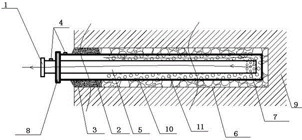
[0025] Such as figure 2 As shown, a coal gas drainage method is used for fragile coal. A drainage pipe 5 is laid from the orifice of the drainage borehole 6 to the bottom of the hole. The front end of the drainage pipe 5 is connected with the hole sealing device, and the end is set The auxiliary drainage hole 7 is connected to the supporting pipe 10 at the end of the plugging device, and the drainage pipe 5 is located in the cavity enclosed by the plugging device and the supporting pipe 10 to prevent coal from squeezing the drainage pipe 5 and blocking the drainage The mining borehole 6, through the drainage of the negative pressure source pipe 1 of the mine drainage system connected with the plugging device, causes the gas in the drainage borehole 6 to flow to the bottom of the drainage borehole 6, from the secondary drainage hole 7 Into the drainage pipe.

[0026] A coal gas drainage device used in the above method includes a negative pressure source pipe 1 connected with a mi...


PUM


Abstract

The invention discloses a coal-mass gas extraction method and device. Negative pressure of a gas extraction system is led to the bottom of a gas extraction drilled hole, the utilization rate of the negative pressure of the gas extraction system is increased, the efficiency of the extraction negative pressure of gas drilled holes can be improved, the concentration of extracted gas in the gas drilled holes can be improved, the extraction time of gas drilled holes is shortened, gas can be utilized fully, and influences of gas on safety production of a coal mine are reduced greatly.

Description

technical field [0001] The invention belongs to the field of coal mine gas safety, in particular to a method for extracting coal gas. The invention also provides a coal body gas extraction device. Background technique [0002] In the process of coal mine safety production, early extraction of gas is an effective way to solve the impact of gas on coal mine safety production. In the process of gas drainage in high-gas mines, due to factors such as equipment, technology, and personnel operations, the pipeline that generates negative pressure is only extended to the vicinity of the hole of the drainage borehole, and the coal mass cannot be drained to the greatest extent. Even if a part of the gas is extracted, the concentration of the gas is low and the drainage time is long, and it is also easily affected by the collapse of the coal body, which leads to the blockage of the drill hole, which not only cannot guarantee the safe production of the coal mine in a short time , the e...

Claims


Application Information

Patent Timeline
IPC IPC(8): E21F7/00
CPCE21F7/00
Inventor 张丽军
Owner 张丽军
Learn More