
Columnar hydraulic tappet

A hydraulic tappet and columnar technology, applied in the direction of engine components, machines/engines, mechanical equipment, etc., can solve the problems of low processing efficiency, multi-process, time-consuming and labor-intensive, etc., to avoid hole processing waste, simple plunger structure, Good processing effect

Active Publication Date: 2015-05-13
HANGZHOU XZB TECH
View PDF7 Cites 5 Cited by
  • Summary
  • Abstract
  • Description
  • Claims
  • Application Information

AI Technical Summary

Problems solved by technology

[0004] Chinese patent document CN102767405 discloses a hydraulic support element. The plunger of this structure is a split structure consisting of two upper and lower plunger bodies. The processing waste produced is easy to clean up; but its disadvantage is that the processing of the two parts separately increases the processing procedure, the processing efficiency is low, and the production cost is high. If the degree is out of tolerance, lateral force will be generated, which may cause the plunger body to be stuck in the housing. The use function of the product should be
In addition, if the plunger oil inlet hole adopts the punching process, sometimes the waste cannot be completely punched off and sticks to the inner wall. process, there may be burrs in the hole on the inner wall, and there is also a risk
[0005] Chinese patent document CN201228569Y discloses a hydraulic support element. The plunger of this structure is an integrated structure, and a steering member is provided inside. The structure of the oil inlet hole determines that the oil inlet hole will inevitably produce waste during processing. Since the plunger cavity of this structure does not have a large enough outlet channel, the waste generated is difficult to completely remove. In addition, the waste generated by hole processing may also be Not completely cut off, but attached to the inner wall of the plunger, making waste removal even more difficult

Method used


Image

  • Columnar hydraulic tappet
  • Columnar hydraulic tappet
  • Columnar hydraulic tappet

Examples


Embodiment 1

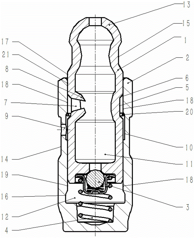
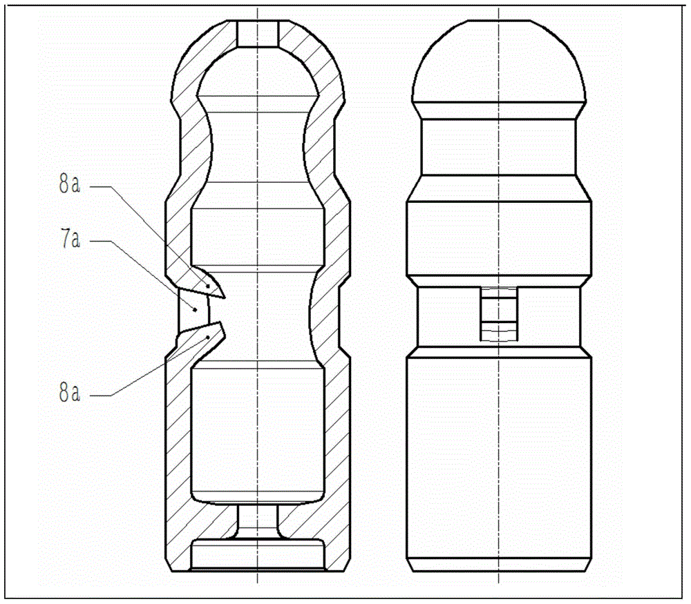
[0053] Such as figure 1As shown, the columnar hydraulic tappet used in the engine valve train has a pot-shaped housing (2), and an axially slidable plunger is arranged in the inner cavity of the housing (2) (1). There is a high-pressure chamber (12) between the lower end surface of the plunger (1) and the housing (2), and the high-pressure chamber (12) can be closed by a one-way valve (3) located at the lower end of the plunger (1). There is a return spring (4) connecting the plunger (1) and the housing (2) in the high-pressure chamber (12). On the outer diameter of the housing (2) there is an outer ring groove (14) for the circulation of the hydraulic medium, and on the radial inner side of the housing (2) there is an inner ring groove (10) for the circulation of the hydraulic medium. One or more oil holes (9) for the circulation of hydraulic medium are provided between the inner ring groove (10) of the housing and the outer ring groove (14) of the housing. The inner wall o...

Embodiment 2

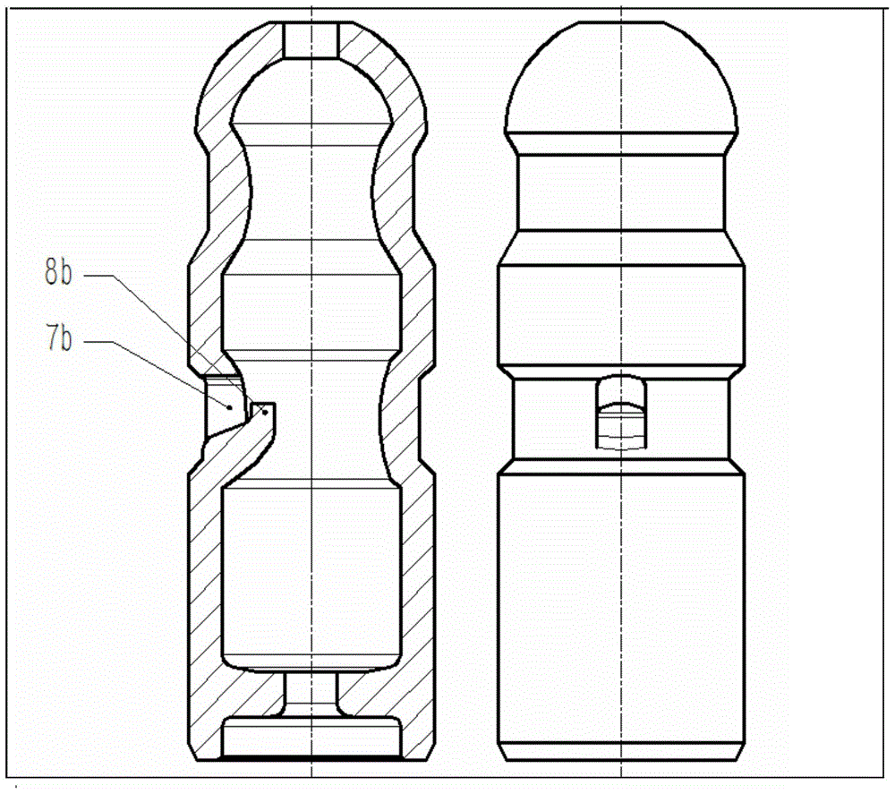
[0059] Such as image 3 As shown, the difference from Embodiment 1 is that the structure of the plunger oil inlet hole (7b) is a single-sided window structure, and the window opening direction is upward.

Embodiment 3

[0061] Such as Figure 4 As shown, the difference from Embodiment 1 is that the structure of the plunger oil inlet hole (7c) is a single-sided window structure, and the window opening direction is downward.


PUM


Abstract

A columnar hydraulic tappet is provided with a shell. A plunger axially moving relative to the shell is correspondingly installed in an inner cavity of the shell. A high pressure cavity for hydraulic media extends between the lower end face of the plunger and the lower side of the shell. The high pressure cavity is closed through a one-way valve opened towards the high pressure cavity. An outer annular groove for circulation of the hydraulic media is formed in the outer diameter of the shell. An inner annular groove for circulation of the hydraulic media is formed in the inner radial side of the shell. One or more shell oil inlets are formed between the inner annular groove and the outer annular groove. A first annular groove is formed in the lower portion of the head of the plunger, a second annular groove is formed in the middle of the plunger, and a plunger middle wall is arranged between the first annular groove and the second annular groove. The second annular groove is an inward-concave wide annular groove. At least one plunger oil inlet is formed in the inward-concave wide annular groove or the middle wall of the plunger. The edge of the bottom of the plunger oil inlet comprises a flange towards the inner cavity of the plunger. The columnar hydraulic tappet is simple in structure and solves the problem that waste inside an inner cavity of an integrated plunger is hard to remove.

Description

technical field [0001] The invention belongs to the technical field of engine parts manufacturing, and in particular relates to a columnar hydraulic lifter capable of automatically compensating the working clearance of valves. Background technique [0002] The valve mechanism using the roller rocker arm and the hydraulic tappet is widely used in the structure of the overhead cam engine. Compared with the valve mechanism of the mechanical tappet, it has the following advantages: 1) It can compensate the valve clearance in real time and does not require regular manual work. Adjustment; 2) Reduce engine noise and impact; 3) Light weight, smaller friction, and smaller moment of inertia mean less energy loss, which is conducive to improving engine efficiency; 4) The life of parts of the valve train Longer and less maintenance cost. [0003] The columnar hydraulic tappet has a pot-shaped housing, and a plunger that moves axially relative to the housing is fitted in the inner cavi...

Claims


Application Information

Patent Timeline
IPC IPC(8): F01L1/245
CPCF01L1/24F01L1/2405F01L1/245F01L2303/00
Inventor 徐纳
Owner HANGZHOU XZB TECH
Learn More