Calibration method of coupling position relationship between micro lens array and detector

A technology of microlens array and calibration method, applied in the field of instrument parameter calibration, can solve the problems of low precision, calibration, poor result stability, etc., and achieve the effect of simple application

Active Publication Date: 2015-05-13
BEIHANG UNIV
View PDF4 Cites 15 Cited by
  • Summary
  • Abstract
  • Description
  • Claims
  • Application Information

AI Technical Summary

Problems solved by technology

This method does not calibrate the distance between the microlens array and the detector, and defaults to the ideal positional relationship, and use...

Method used


Image

  • Calibration method of coupling position relationship between micro lens array and detector
  • Calibration method of coupling position relationship between micro lens array and detector
  • Calibration method of coupling position relationship between micro lens array and detector

Examples


Embodiment Construction

[0018] The present invention will be further described in detail with reference to the accompanying drawings and embodiments.

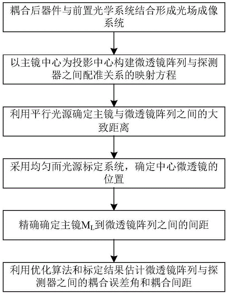
[0019] The present invention is a method for calibrating the coupling position relationship parameters for the microlens array and the detector coupling device, the process is as follows figure 1 shown, including the following steps:

[0020] Step 1: Combining the microlens array and the detector coupled device with the pre-optical system to form a light field imaging system.

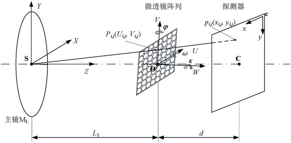
[0021] Coupling the microlens array and the detector, the ideal distance between the two is the focal length f of the microlens m , the actual distance is d, which is the parameter to be calibrated. There are inclination and oblique angles between the plane where the coupled microlens array is located and the plane where the detector is located, that is, the following coupling rotation error angle , ω, κ are also parameters to be calibrated. The coupled device is combined ...


PUM


Abstract

The invention discloses a calibration method of a coupling position relationship between a micro lens array and a detector. The calibration method of the coupling position relationship between the micro lens array and the detector includes: combining a device formed by coupling the micro lens array and the detector with a front optical system into a light field imaging system; building a mapping equation between the center of micro lenses and a point pi,j on a plane of the detector based on a central projection principle; using a parallel light source to confirm a rough distance between a main lens and the micro lens array; using a uniform area light source to calibrate the light field imaging system, and confirming an actual coordinate of the point pi,j on the plane of the detector; confirming accurate value of L1; using an optimization algorithm to estimate coupling error angles phi, omega, k and d between the micro lens array and the detector. The calibration method of the coupling position relationship between the micro lens array and the detector only needs to roughly confirm a position relationship between the micro lens array and the front optical system in the light field imaging system, cam achieve calibration of parameters of a distance, a rotation angle and the like between the micro lens array and the detector, is simple to use, and facilitates actual operation.

Description

technical field [0001] The invention relates to optical imaging technology and belongs to the technical field of instrument parameter calibration, in particular to a calibration method for the coupling position relationship between a microlens array and a detector. Background technique [0002] The light field camera (Plenoptic Camera) based on light field imaging technology is composed of a front optical system and a rear optical system. The rear optical system is formed by coupling a microlens array and a detector, and the distance between the two is the focal length of the microlens. In addition, the Shack-Hartmann wavefront sensor is coupled by a microlens array and a detector, and the distance between the two is also the focal length of the microlens. Both the accuracy of the light field information extracted from the light field camera and the accuracy of the wavefront measurement using Shack-Hartmann are affected by the coupling positional relationship between the mic...

Claims


Application Information

Patent Timeline
IPC IPC(8): G01B11/00
Inventor 苏丽娟袁艳周建
Owner BEIHANG UNIV
Why Eureka
Try Eureka