Stage laser positioning calibration device and stage laser positioning calibration method

A laser positioning and calibration device technology, applied in the field of positioning, can solve the problems of expensive camera, affecting positioning, complex processing process, etc., and achieve the effect of simple structure, fast positioning and calibration, and convenient calibration operation

Inactive Publication Date: 2015-05-13
GUANGDONG VTRON TECH CO LTD
View PDF5 Cites 15 Cited by
  • Summary
  • Abstract
  • Description
  • Claims
  • Application Information

AI Technical Summary

Problems solved by technology

Although this solution solves the defects of traditional adhesive plaster markings, etc., it needs to use an infrared low-light camera to feed back the specific position effect, the camera is expensive, and most of the existing cameras have no night vision function, even if there is a night vision Vision function, the camera has a large error in shooting in the dark, which will still affect the positioning
In addition, after the infrared low-light camera captures the laser projection effect on the stage, image analysis is required, and the processing process is complicated

Method used


Image

  • Stage laser positioning calibration device and stage laser positioning calibration method
  • Stage laser positioning calibration device and stage laser positioning calibration method
  • Stage laser positioning calibration device and stage laser positioning calibration method

Examples


Embodiment 1

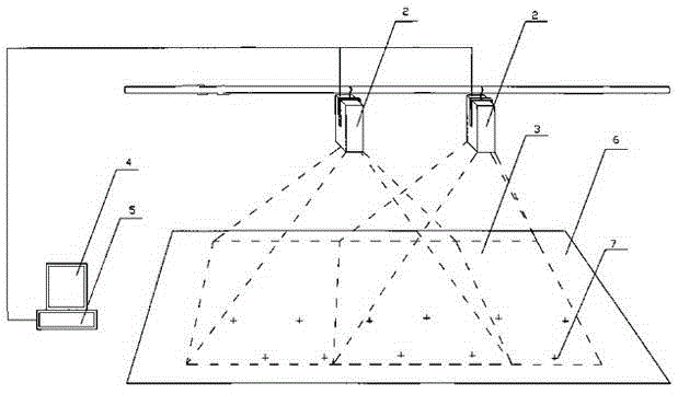
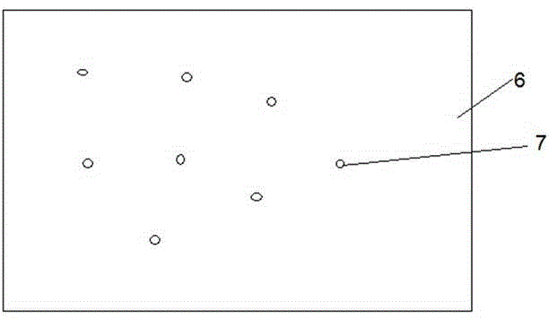
[0032] Such as figure 1 As shown, it is a structural diagram of a specific embodiment of a stage laser positioning and calibration device according to the present invention. see figure 1 In this specific embodiment, a stage laser positioning calibration device specifically includes a main control operator 5, a display 4 and a laser scanning transmitter 2 installed above the stage 6, and the main control operator 5 is connected to the display 4 and the laser scanning transmitter 2 respectively. The connection also includes a locator 7 placed on the positioning object and a positioning data receiver wirelessly connected to the locator 7, and the positioning data receiver is connected to the master operator 5.

[0033] In this specific embodiment, the main control operator 5 controls the laser scanning transmitter 2 to emit laser light onto the stage 6 for position marking, the positioning object stands according to the position marking on the stage 6, and the positioning object...

Embodiment 2

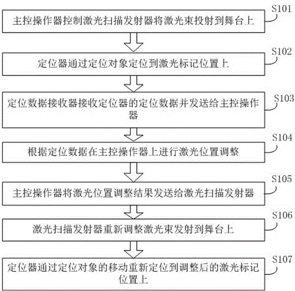
[0039]On the basis of Embodiment 1, the present invention also provides a stage laser positioning calibration method. see figure 2 , is a flowchart of a specific embodiment of a stage laser positioning and calibration method according to the present invention. In this specific embodiment, the stage laser positioning and calibration device described in Embodiment 1 is used to implement.

[0040] Such as figure 2 As shown, a stage laser positioning calibration method in this specific embodiment specifically includes the following steps:

[0041] S101. The main control operator controls the laser scanning transmitter to project the laser beam onto the stage;

[0042] S102. The locator locates the laser marking position through the positioning object;

[0043] S103. The positioning data receiver receives the positioning data of the locator and sends it to the main control operator;

[0044] S104. Perform laser position adjustment on the main control operator according to the...


PUM


Abstract

The invention relates to the field of positioning, and particularly relates to a stage laser positioning calibration device and a stage laser positioning calibration method. The device comprises a master control manipulator, a display and a laser scanning transmitter installed above a stage, wherein the master control manipulator is connected with the display and the laser scanning transmitter respectively. The device also comprises a positioner arranged on a positioning object and a positioning data receiver in wireless connection with the positioner, wherein the positioning data receiver is connected with the master control manipulator. According to the stage laser positioning calibration device and the stage laser positioning calibration method provided by the invention, the defect that a laser projection effect is affected by stage light when a camera is adopted for shooting the stage can be overcome, the high cost of the camera is saved and an image analysis step which is needed after the camera is used for shooting images is omitted, and the entire calibration device is simple in structure, convenient for calibration operation, high in positioning and calibration speeds, and low in cost.

Description

technical field [0001] The present invention relates to the field of positioning, and more particularly, to a stage laser positioning calibration device and method. Background technique [0002] At present, the known stage positioning marks are carried out by means of adhesive plaster, post-it notes, pasting with colored pens, sketching, etc. Most of the cameras on the stage do not have night vision functions, and even if they have night vision functions, the positioning is not accurate. It is difficult for actors and dancers to accurately find the predetermined position under the state of black light on the stage. They can only find the positioning marks with the help of low light. In addition, during multi-scene performances, each scene mark overlaps with each other, making it more difficult to accurately find the predetermined position. Especially on the stage of the TV studio theater, the messy positioning marks also cause direct pollution to the TV screen, seriously af...

Claims


Application Information

Patent Timeline
Patent Type & Authority Applications(China)
IPC IPC(8): G01C21/00G01C15/00
CPCG01C25/00
Inventor 刘雄伟
Owner GUANGDONG VTRON TECH CO LTD
Why Eureka
Try Eureka