
Appearance welding spot protecting device

A technology for protection devices and solder joints, applied in welding protection devices, auxiliary devices, welding accessories, etc., can solve problems such as single copper plate surface, small effective welding space, and difficult electrode maintenance, so as to reduce requirements, facilitate maintenance, and ensure The effect of surface conformity

Active Publication Date: 2015-05-20
CHONGQING CHANGAN AUTOMOBILE CO LTD
View PDF5 Cites 8 Cited by
  • Summary
  • Abstract
  • Description
  • Claims
  • Application Information

AI Technical Summary

Problems solved by technology

The existing solder joint protection device is usually a cage structure installed on the electrode head of the welding tongs. This structure can protect the solder joints to a certain extent, but there are still problems: Problem 1, the solder joint protection device and sheet metal The matching copper plate has a single surface, which cannot meet the protection of solder joints of different shapes; problem 2, the electrode head needs to be polished, repaired, and replaced in real time during the manufacturing process, but this structure covers the electrode head and protects the electrode. brought many difficulties
Question 3. The effective welding space where many appearance solder joints are located is small. Compared with the space required for electrode head welding, the existing cage protection device requires a larger effective welding space

Method used


Image

  • Appearance welding spot protecting device
  • Appearance welding spot protecting device
  • Appearance welding spot protecting device

Examples


Embodiment Construction

[0016] Further illustrate structure of the present invention below in conjunction with accompanying drawing:

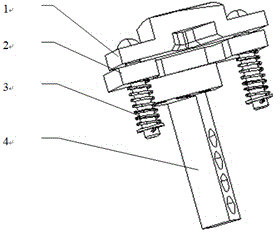
[0017] see figure 1 , The present invention consists of a protective copper pad 1, a connecting plate 2, a spring-type guide pin 3 and a support seat 4.

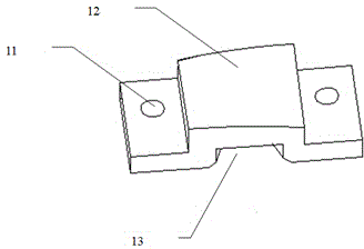
[0018] see figure 2 The protective copper pad 1 is made of chromium-zirconium copper (CuCrZr), and its shape is a few characters. The top surface is the sheet metal contact surface 12 that fits the sheet metal surface, and the bottom surface corresponding to the top surface is the electrode contact surface 13 of the welding tongs. , the sheet metal fitting surface 12 is required to be processed to be consistent with the sheet metal profile data, and the bonding electrode contact surface 13 is required to be similar to the sheet metal profile surface to prevent the electrodes of the welding tongs from sliding. Both ends of the protective copper pad 1 have guide pin holes 11 respectively.

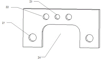
[0019] see image 3 , ...


PUM


Abstract

The invention provides an appearance welding spot protecting device. The appearance welding spot protecting device comprises a protecting copper pad, a connecting plate, guide pins with springs and a supporting seat; the protecting copper pad is shaped like a Chinese character 'ji', the top surface of the protecting copper pad is a sheet metal contact surface attached to a sheet metal molded surface, the bottom surface corresponding to the top surface is an electrode holder electrode contact surface, and the electrode holder electrode contact surface is close to the sheet metal contact surface; the two ends of the protecting copper pad are connected with the connecting plate through the guide pins with springs; the connecting plate is of a door type structure which is placed horizontally, the two edges of the door type structure are connected with the two ends of the protecting copper pad, an electrode holder avoiding channel is left between the door type structure and the protecting copper pad, the door top edge of the connecting plate is connected with the supporting seat, the supporting seat is provided with fastening bolt connecting via holes fixedly connected with a fixture, and the fastening bolt connecting via holes are used for fixing the whole device on the fixture. According to the appearance welding spot protecting device, an electrode on one side of the protected surface preferentially makes contact with the protecting copper pad, and then the protecting copper pad makes contact with sheet metal; because the contact area of the protecting copper pad with the sheet metal is much larger than the contact area of the electrode with the sheet metal, pressure can be dispersed well, and therefore it is guaranteed that a welding spot is not distorted, and the welding spot indentation can meet the appearance quality requirements.

Description

technical field [0001] The invention is applicable to the protection of the appearance solder joints of automobiles, and is a device for preventing defects such as distortion and indentation of the appearance solder joints. Background technique [0002] The exposed solder joints on the outer surface of automobile sheet metal are collectively referred to as appearance solder joints. The surface where these solder joints are located is divided into flat surfaces and some are curved surfaces. Without additional protection measures for solder joints, the welding electrode will bring high pressure due to the impact of the welding electrode on the automobile sheet metal, and the contact area between the electrode and the sheet metal is small. The pressure per unit area of ​​the gold protected surface is relatively large, resulting in stress concentration in the solder joint area, and defects such as excessive solder joint distortion and deep indentation often occur, which cannot m...

Claims


Application Information

Patent Timeline
Patent Type & Authority Applications(China)
IPC IPC(8): B23K37/00
CPCB23K9/321
Inventor 赵宁龙汤艳刚赵硕朱凯
Owner CHONGQING CHANGAN AUTOMOBILE CO LTD
Learn More