Super wear-resistant compound vertical mill roller shell and manufacture method thereof

A vertical grinding roller sleeve, super wear-resistant technology, applied in the casting field, can solve the problems of peeling off blocks, high maintenance costs, etc., to achieve the effect of eliminating blocks and shortening the production cycle

Inactive Publication Date: 2015-05-20
天津泰铭医疗技术股份有限公司
View PDF7 Cites 13 Cited by
  • Summary
  • Abstract
  • Description
  • Claims
  • Application Information

AI Technical Summary

Problems solved by technology

[0009] 2. There is a phenomenon of peeling

Method used


Image

  • Super wear-resistant compound vertical mill roller shell and manufacture method thereof
  • Super wear-resistant compound vertical mill roller shell and manufacture method thereof
  • Super wear-resistant compound vertical mill roller shell and manufacture method thereof

Examples


Embodiment 1

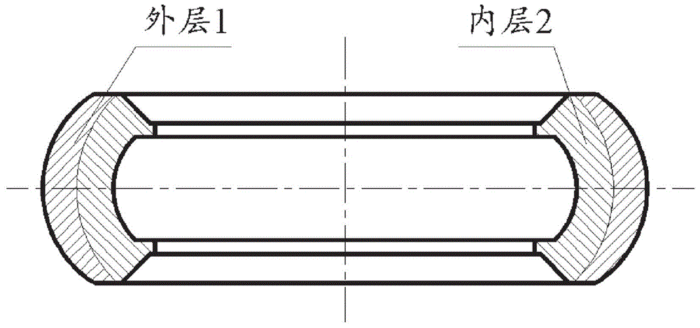
[0042] Such as figure 1 Shown is a cross-sectional view of a super wear-resistant composite vertical mill roll sleeve according to a specific embodiment of the present invention, and the super wear-resistant composite vertical grinder roll sleeve includes a super wear-resistant outer layer 1 and a high-toughness inner layer 2, the outer layer is metallurgically cast super wear-resistant cast iron, the outer layer has carbide sites with a content greater than 35%, and the inner layer is high-toughness medium-carbon low-alloy steel. That is, the outer layer is a wear-resistant layer, and the inner layer is a high-toughness layer.

[0043] Wherein, the carbide points are point-like carbides formed by alloying elements, and the average microhardness of the carbide points is ≥HV2700.

[0044] Preferably, the carbide points are dispersed in the super wear-resistant cast iron.

[0045] Further preferably, the super wear-resistant outer layer is metallurgically combined with the hig...

Embodiment 2

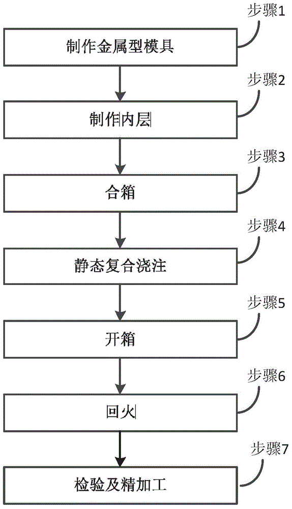
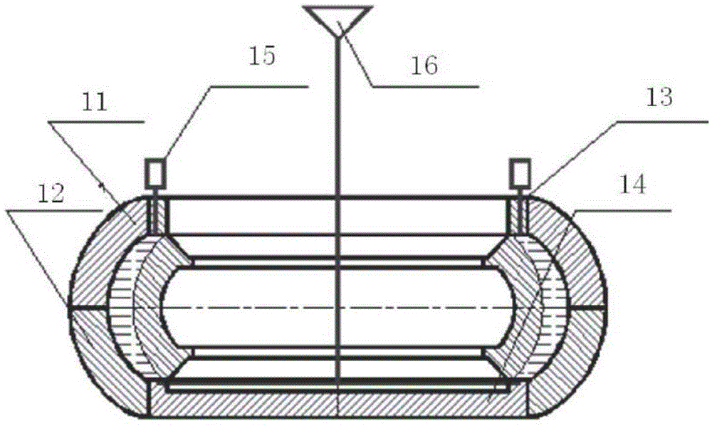
[0049] In this embodiment, the present invention also discloses a preparation method that can be used to manufacture the super wear-resistant composite vertical mill roll sleeve described in Embodiment 1. see figure 2 , shows the flow chart of the preparation method of the super wear-resistant composite vertical mill roll sleeve, see image 3 , which shows a schematic diagram of the pouring system for making super wear-resistant composite vertical mill roll sleeves.

[0050] Described preparation method comprises the steps:

[0051] Step 1. Making a metal mold, wherein the metal mold adopts static casting, and the material is gray iron. Process and produce metal molds according to the requirements of the drawings;

[0052] Step 2. Make the inner layer: use high-toughness medium-carbon low-alloy steel as the inner layer material. The outer surface of the inner layer is processed with 2mm sharp lines, and the inner layer is heated to 930°C and kept for 3 hours;

[0053] Ste...


PUM


Abstract

The invention discloses a super wear-resistant compound vertical mill roller shell. The super wear-resistant compound vertical mill roller shell comprises a dual-layer structure including a super wear-resistant outer layer and a high toughness inner layer, wherein the outer layer is the super wear-resistant cast iron of which the metallurgical melting content is greater than 35% of carbide particle, the inner layer is the high toughness medium carbon low alloy steel, the super wear-resistant outer layer and the high toughness inner layer are bonded together in a metallurgical bonding mode, the wear-resistant cast iron is the super wear-resistant cast iron comprising carbon element more than ordinary level and various alloy elements with ultrahigh content. The working layer molten iron is tightly surrounded by the inner layer which is heated to 930 DEG C under the static pressure, with washing action of the molten iron, the outer surface forming boundary of the inner layer jacket with deep sharp lines of 2mm is melted, and the outer layer and the inner layer can be bonded together in the metallurgical bonding mode along the reduction of the temperature; the failure mode as piece dropping and spalling due to the welding of micro cracks can be thoroughly eliminated and the maintenance-free is achieved for life.

Description

technical field [0001] The invention belongs to the field of casting, and in particular relates to a super wear-resistant composite vertical mill roller sleeve and a manufacturing method thereof. Background technique [0002] Most of the existing vertical mill roller sleeves are of the structure of "cast medium carbon steel + outer surfacing wear-resistant layer". Its preparation method comprises the following steps: [0003] 1. First, medium carbon steel is used to make the vertical grinding roller sleeve; [0004] 2. Then carry out the normalizing heat treatment of the roller sleeve body; [0005] 3. Rough machining of the roller sleeve; [0006] 4. Surfacing a wear-resistant layer with a thickness of about 15-50mm on the outer surface of the roller sleeve. [0007] There are problems in the structure and preparation method of the existing vertical mill roller sleeve: [0008] 1. The thickness of the surfacing layer is thin and the wear resistance is poor, and the ser...

Claims


Application Information

Patent Timeline
IPC IPC(8): C22C37/10C22C38/18B22D19/16B02C15/00
Inventor 王文祥柳长沼
Owner 天津泰铭医疗技术股份有限公司
Why Eureka
Try Eureka