Drilling machine angle accurate positioning detection and control system

A technology with accurate angle and positioning detection, applied in the automatic control system of drilling, rotary drilling rig, drilling equipment and method, etc., can solve the problems of wellbore trajectory control failure, drilling tool face drift, affecting operation time and other problems. Achieve the effect of saving manpower and material resources, shortening drilling cycle and improving drilling efficiency

Inactive Publication Date: 2015-05-20
SICHUAN HONGHUA ELECTRIC
View PDF7 Cites 8 Cited by
  • Summary
  • Abstract
  • Description
  • Claims
  • Application Information

AI Technical Summary

Problems solved by technology

[0002] In conventional drilling operations, the vertical well section and the stabilizing section are usually drilled by top drive or rotary drilling, and if the steering drilling section uses the downhole angled deflection power drilling tool, the sliding drilling method is usually used. Under the conditions of adjustment, stratum lithology change, power drilling tool wear and other conditions, it is easy to cause drilling tool face drift, resulting in failure of wellbore trajectory control and other problems
Faced with this situation, the usual practice is to reset the tool face by stopping drilling and lifting the drilling tool after the downhole tool face has drifted, which will affect the operating timeliness
At the same time, in the sliding drilling process of conventional steerable drilling tools, because the drilling tool cannot rotate, the application of drilling pressure is delayed, the wellbore cleaning is difficult, and it is easy to cause problems such as low operating efficiency and complicated procedures.

Method used


Image

  • Drilling machine angle accurate positioning detection and control system
  • Drilling machine angle accurate positioning detection and control system
  • Drilling machine angle accurate positioning detection and control system

Examples


Embodiment 1

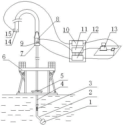
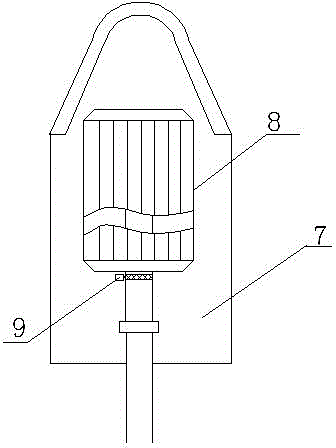
[0022] Such as figure 1 and figure 2 As shown, a drilling rig angle precise positioning detection and control system, which includes a drive system, a detection device and an actuator corresponding to the drive system;

[0023] The detection device includes MWD system pressure signal sensor 15, tool face decoder 10, dynamic tool face controller 13, servo and braking system 11, angle detection device and angle signal processor 12, MWD system pressure signal sensor 15 The output is connected to the tool surface decoder 10, the output of the tool surface decoder 10 is connected to one input of the dynamic tool surface controller 13, the output of the dynamic tool surface controller 13 is connected to the servo and braking system 11, and the servo and braking system 11 is connected to the drive system, the output of the angle detection device is connected to the angle signal processor 12, and the output of the angle signal processor 12 is connected to another input of the dynami...

Embodiment 2

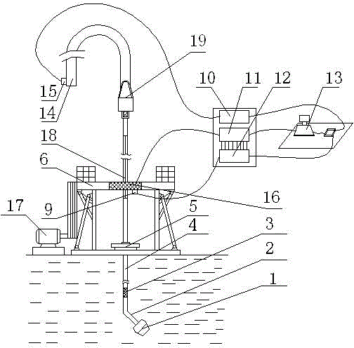
[0036] Such as image 3 and Figure 4 As shown, a drilling rig angle precise positioning detection and control system, which includes a drive system, a detection device and an actuator corresponding to the drive system;

[0037]The detection device includes MWD system pressure signal sensor 15, tool face decoder 10, dynamic tool face controller 13, servo and braking system 11, angle detection device and angle signal processor 12, MWD system pressure signal sensor 15 The output is connected to the tool surface decoder 10, the output of the tool surface decoder 10 is connected to one input of the dynamic tool surface controller 13, the output of the dynamic tool surface controller 13 is connected to the servo and braking system 11, and the servo and braking system 11 is connected to the drive system, the output of the angle detection device is connected to the angle signal processor 12, and the output of the angle signal processor 12 is connected to another input of the dynamic...

Embodiment 3

[0050] Such as Figure 5 As shown, a drilling rig angle precise positioning detection and control system, which includes a drive system, a detection device and an actuator corresponding to the drive system;

[0051] The detection device includes MWD system pressure signal sensor 15, tool face decoder 10, dynamic tool face controller 13, servo and braking system 11, angle detection device and angle signal processor 12, MWD system pressure signal sensor 15 The output is connected to the tool surface decoder 10, the output of the tool surface decoder 10 is connected to one input of the dynamic tool surface controller 13, the output of the dynamic tool surface controller 13 is connected to the servo and braking system 11, and the servo and braking system 11 is connected to the drive system, the output of the angle detection device is connected to the angle signal processor 12, and the output of the angle signal processor 12 is connected to another input of the dynamic tool surface...


PUM


Abstract

The invention discloses a drilling machine angle accurate positioning detection and control system. The drilling machine angle accurate positioning detection and control system comprises a driving system, a detection device and an actuator corresponds to the driving system, wherein the driving system comprises a top driving system or a rotary disk driving system. The drilling machine angle accurate positioning detection and control system has the advantages that the adopted angle detection device can automatically calculate the rotating angle of a rotating shaft of a motor, calculation is accurate, the accuracy is high, the anti-seismic property is good, machining is easy, and cost is low; since a dynamic tool face controller is used for achieving dynamic control over a downhole orientation power drilling tool face, when the drilling tool face drifts, the dynamic tool face controller can be operated in real time to adjust the drilling tool face, and the situation that equipment stops drilling and a drilling tool is lifted up is avoided; as a result, loss of the equipment is reduced, manpower and material resources are saved substantially, and downhole accidents are greatly reduced at the same time.

Description

technical field [0001] The invention relates to a detection and control system for precise positioning of downhole tool face angles, in particular to a detection and control system for precise positioning of drilling rig angles. Background technique [0002] In conventional drilling operations, the vertical well section and the stabilizing section are usually drilled by top drive or rotary drilling, and if the steering drilling section uses the downhole angled deflection power drilling tool, the sliding drilling method is usually used. Under conditions such as adjustment, formation lithology changes, and wear and tear of dynamic drilling tools, it is easy to cause drilling tool face drift, resulting in failure of wellbore trajectory control and other problems. Faced with this situation, the usual practice is to reset the tool face by stopping drilling and lifting the drilling tool after the downhole tool face has drifted, which will affect the operating timeliness. At the s...

Claims


Application Information

Patent Timeline
Patent Type & Authority Applications(China)
IPC IPC(8): E21B44/00E21B47/02E21B47/06E21B47/12E21B7/04E21B3/02E21B3/04
Inventor 王江阳李汉兴武广瑷邓果魏仕海于东奎
Owner SICHUAN HONGHUA ELECTRIC
Why Eureka
Try Eureka