Non-contact vibrationless low-temperature solid interface thermal resistance testing arrangement

A test device and solid interface technology, applied in the field of thermophysical properties of high-temperature superconducting materials, can solve the problems of small independent sealed space and long experiment time, and achieve the effect of shortening the experiment period, reducing the impact, and reducing the time for vacuuming

Inactive Publication Date: 2015-05-20
NAVAL UNIV OF ENG PLA
View PDF3 Cites 16 Cited by
  • Summary
  • Abstract
  • Description
  • Claims
  • Application Information

AI Technical Summary

Problems solved by technology

[0004] In view of the above defects or improvement needs of the prior art, the present invention provides a low-temperature solid interface thermal resistance testing device, the purpose of which is to provide

Method used


Image

  • Non-contact vibrationless low-temperature solid interface thermal resistance testing arrangement
  • Non-contact vibrationless low-temperature solid interface thermal resistance testing arrangement
  • Non-contact vibrationless low-temperature solid interface thermal resistance testing arrangement

Examples


Embodiment Construction

[0034] In order to make the object, technical solution and advantages of the present invention clearer, the present invention will be further described in detail below in conjunction with the accompanying drawings and embodiments. It should be understood that the specific embodiments described here are only used to explain the present invention, not to limit the present invention. In addition, the technical features involved in the various embodiments of the present invention described below can be combined with each other as long as they do not constitute a conflict with each other.

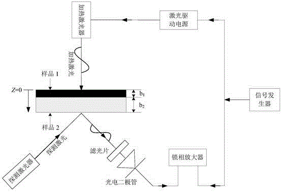
[0035] Such as figure 1Shown is a schematic diagram of the principle of measuring interface thermal resistance by laser photothermal method. During the experiment, the two sample pieces are stacked together and installed in the sample fixture. The signal generator generates a modulation signal of a certain frequency and divides it into two signals. One is used as a reference signal to input the...


PUM


Abstract

The invention discloses a low-temperature solid interface thermal resistance testing arrangement. An upper end of a lower bellows and a lower end of an upper bellows are fixed in a sealed manner at an opening of an upper end of a vacuum cap; a seal cover covers the upper end of the upper bellows; the upper surface of the lower end of the lower bellows is connected to a lower surface of a bottom of a sample holder through a flexible cold guide structure; the lower end of the lower bellows contacts an upper surface of a cold head of a refrigerating machine; the upper end of the upper bellows, the upper end of the sample holder and the seal cover are tightly fixed to a vibration isolation support; and an enclosed space is formed by the upper bellows, the lower bellows and the seal cover, and is internally provided with a sample clamp, which is arranged at the bottom of the sample support and is used for mounting a sample to be detected. According to the structure in the invention, a vacuum environment can be formed in the enclosed space for the air in the enclosed space can be quickly pumped out; vacuum-pumping time and cooling time are reduced during sample replacement; and an experimental period is shortened. The upper end of the sample support is tightly connected to the vibration isolation support, and the bottom of the sample support is connected to the lower end of the lower bellows through the flexible cold guide structure, so that influence of cold head vibration on the sample support when the refrigerating machine works is avoided.

Description

technical field [0001] The invention belongs to the research field of thermophysical properties of high-temperature superconducting materials, and in particular relates to a non-contact and vibration-free low-temperature solid interface thermal resistance testing device. Background technique [0002] The test of interface thermal resistance at low temperature is crucial to the heat transfer analysis of materials under conduction cooling conditions, and the accuracy of the test is directly related to the stability and reliability of the system. At present, the methods of interface thermal resistance can be divided into steady-state method and transient method. The traditional steady-state method has a long test period, the heat flow is not easy to control, and a large-sized sample is required to arrange the sensor. As a transient testing method, the laser photothermal method greatly shortens the test period, has the characteristics of small test sample size and non-contact, ...

Claims


Application Information

Patent Timeline
IPC IPC(8): G01N25/20
Inventor 吴钢李想汤智胤毕柯李雁飞张青枝
Owner NAVAL UNIV OF ENG PLA
Why Eureka
Try Eureka