Power supply switch control circuit with power down delay function

A power switch, control circuit technology, applied in electrical program control, circuit or fluid pipeline, program control in sequence/logic controllers, etc. Delay time change and other problems, to achieve the effect of configurability, free setting of power-off delay time, and easy cost

Inactive Publication Date: 2015-05-20
CHONGQING JINMEI COMM
View PDF4 Cites 10 Cited by
  • Summary
  • Abstract
  • Description
  • Claims
  • Application Information

AI Technical Summary

Problems solved by technology

[0004] At present, most of the delayed power-down circuits adopt RC circuit structure, and the power-down time is determined by the value of R and C. Once the RC circuit is determined, the power-down time cannot be changed at will, and the resistance R and capacitance C change with the ambient temperature. Larger, it will cause the change of the delay time, and it cannot be precisely controlled

Method used


Image

  • Power supply switch control circuit with power down delay function

Examples


Embodiment Construction

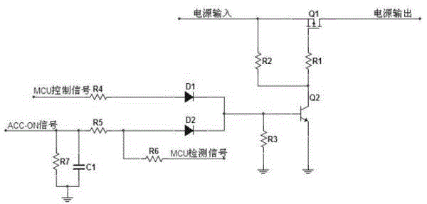
[0009] The invention proposes a power switch control circuit with a power-off delay function, which solves the power supply control problem of the controller from the aspects of power-off delay, dark current reduction and the like. figure 1 It is a circuit disclosed by the invention, and the circuit includes two parts of a level conversion and a power switch.

[0010] The level conversion circuit is composed of C1, D1, D2, R3, R4, R5, and R6. In the power supply system of the vehicle, the standard voltage is generally 12V, so the key signal level is also around 12V, and C1 is here Filter the external key signal. R3, R5, and D2 form a voltage divider circuit to provide a suitable drive level for the conduction of Q2. R6 is the current limiting resistor for the signal to prevent the IO port of the MCU from being burned by excessive current. . R3, R4, and D1 form a voltage divider circuit for the MCU control signal, which is the same as the aforementioned voltage divider circuit...


PUM


Abstract

The invention discloses a power supply switch control circuit with the power down delay function. The circuit is particularly adaptive to constant powered and MCU circuits. On the condition of omitting a special power supply chip, the power down delay function of the entire circuit can be realized simply. The circuit is simple in structure and is divided into two portions, namely an input level conversion portion and a power supply switching circuit portion.

Description

technical field [0001] The invention relates to the automobile electronic technology, in particular to the power supply circuit part in the automobile controller. Background technique [0002] With the continuous development of automotive electronic technology, there are more and more electronic control units in the vehicle, such as electronically controlled fuel injection system (ECU), anti-lock braking system (ABS) and so on. These electronic control units are the brains that control the driving of the car. When the driver turns off the engine, if the electronic control unit is powered off immediately, some important data may not be saved; on the other hand, if the electronic control unit is suddenly powered off without Some safety operations will not ensure that the vehicle transmission system can be in a safe position after parking, so there will be serious safety hazards when the vehicle starts next time, such as the AMT unit of the car, which is the core of controlling...

Claims


Application Information

Patent Timeline
Patent Type & Authority Applications(China)
IPC IPC(8): G05B19/04B60R16/02
CPCB60R16/0231
Inventor 肖颖曾亚军李鸿姜超
Owner CHONGQING JINMEI COMM
Why Eureka
Try Eureka