Band-gap reference circuit

A reference circuit and resistor technology, applied in the direction of adjusting electrical variables, control/regulation systems, instruments, etc., can solve problems such as large overshoot of reference voltage, and achieve the effect of improving reliability

Active Publication Date: 2015-05-20
SPREADTRUM COMM (SHANGHAI) CO LTD
View PDF9 Cites 11 Cited by
  • Summary
  • Abstract
  • Description
  • Claims
  • Application Information

AI Technical Summary

Problems solved by technology

[0008] The present invention solves the problem that the reference voltage output by the bandgap reference circuit has a large overshoot when starting

Method used


Image

  • Band-gap reference circuit
  • Band-gap reference circuit
  • Band-gap reference circuit

Examples


Embodiment Construction

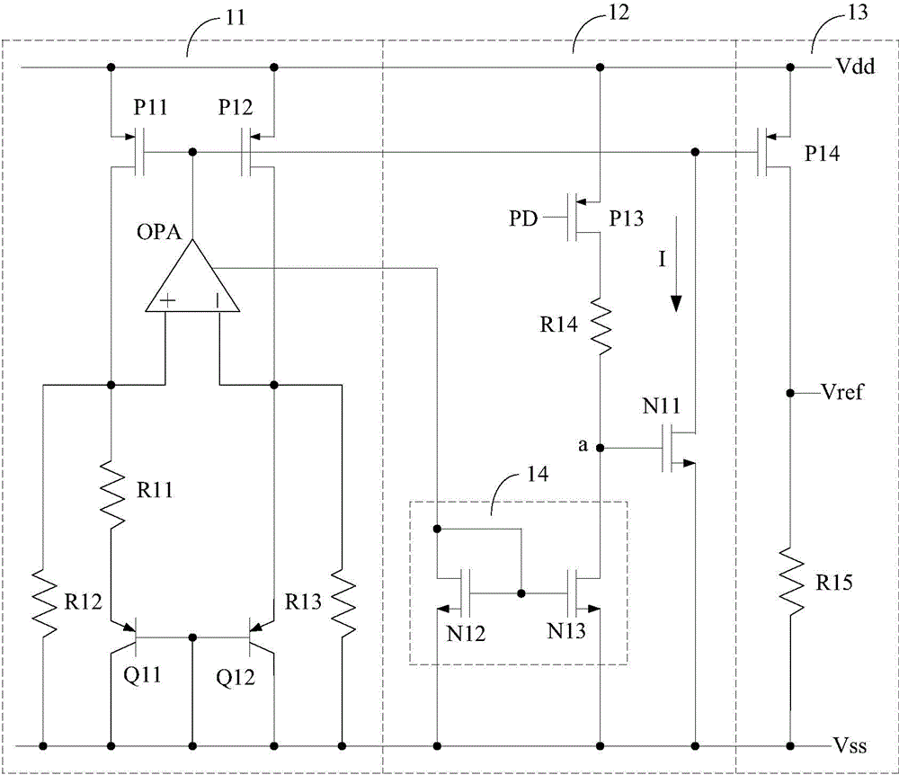
[0040] reference figure 1 The starting process of the existing bandgap reference circuit is as follows:

[0041] After the circuit system where the bandgap reference circuit is located is powered on, that is, after the first power line Vdd and the second power line Vss provide a power supply voltage, a bias voltage is applied to the gate of the third PMOS transistor P13 PD, the third PMOS transistor P13 is turned on, and the power supply voltage on the first power line Vdd charges the node a through the third PMOS transistor P13 and the fourth resistor R14 (the node a is The fourth resistor R14, the drain of the third NMOS transistor N13, and the gate connection point of the first NMOS transistor N11), so that the potential of the node a continuously rises;

[0042] When the potential of the node a is higher than the threshold voltage of the first NMOS tube N11, the first NMOS tube N11 is turned on, and the gate potential of the first PMOS tube P11 and the second PMOS tube The gat...


PUM


Abstract

The invention provides a band-gap reference circuit. The band-gap reference circuit comprises a band-gap core unit, a starting unit, an output unit and a clamping unit, wherein the starting unit comprises a first PMOS tube, a first resistor, a current-limiting diode, a first NMOS tube and a circuit mirror unit; the clamping unit is applicable to conduct clamping on a grid electrode of the first NMOS tube. According to the technical scheme, the reference voltage provided by the band-gap reference circuit is small in overshoot when being started and improves the reliability of a circuit system.

Description

Technical field [0001] The present invention relates to the technical field of integrated circuits, in particular to a band gap reference circuit. Background technique [0002] The bandgap reference circuit has the advantages of low temperature coefficient, low power supply voltage and compatibility with standard CMOS technology, and is widely used in digital-analog hybrid circuit systems such as digital / analog conversion, analog / digital conversion, memory, and switching power supply. The stability of the output voltage of the bandgap reference circuit and the ability to resist noise are the key factors that affect the accuracy of various application systems. With the improvement of the accuracy of the application system, the temperature, voltage and process stability requirements of the bandgap reference circuit are also increasing. Higher. [0003] The working principle of the band gap reference circuit is based on the temperature-independent characteristics of the band gap volt...

Claims


Application Information

Patent Timeline
Patent Type & Authority Applications(China)
IPC IPC(8): G05F3/26
Inventor 沈海峰
Owner SPREADTRUM COMM (SHANGHAI) CO LTD
Why Eureka
Try Eureka