Metal laser tube

A laser tube and metal technology, applied in the field of laser tubes, can solve the problems of easily broken customers, inconvenient recycling, loss, etc., and achieve the effect of firm overall structure, not easy to break, and good convenience

Inactive Publication Date: 2015-05-20
陈海榕
View PDF3 Cites 3 Cited by
  • Summary
  • Abstract
  • Description
  • Claims
  • Application Information

AI Technical Summary

Problems solved by technology

[0005] The invention provides a metal laser tube that is not easy to break, easy to manufacture, and forms a cooling chamber and a gas storage chamber without sintering, which solves the problem that the existing glass-structured laser tube is easy to break and causes losses to customers, and is not easy to recycle and reuse. The problem that a large amount of harmful gas will be generated during the production process

Method used


Image

  • Metal laser tube
  • Metal laser tube
  • Metal laser tube

Examples


Embodiment 1

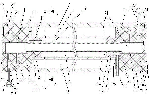
[0024] Embodiment one, see figure 1 , a metal laser tube, including a glass discharge tube 1, an anode end support seat 2, a cathode end support seat 3, a metal inner tube 4 and a metal outer tube 5.

[0025]The anode end support seat 2 is made of insulating material, such as ceramics. The anode end support seat 2 is provided with an anode end channel 21 . The anode end support base 2 is provided with an anode end support base 20 and a first protrusion 22 of the anode end support base located at one end of the anode end support base. The end surface of the first protruding head 22 of the anode end support seat is provided with a second protruding head 23 of the anode end support seat. The anode end channel 21 runs through the end surface 201 of the base of the anode end support seat and the end surface 231 of the second protrusion of the anode end support seat. The anode end support base 2 is provided with an anode wire lead-out hole 24 . The outer port 241 of the lead-out...

Embodiment 2

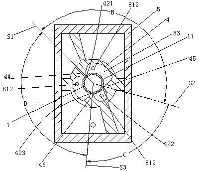
[0034] Embodiment two, see figure 2 , the difference with the first embodiment is: the inner tube 4 is circular. The inner surface of the inner tube 4 is provided with a first rib 44 , a second rib 45 and a third rib 46 . The first rib 44 and the outer surface 11 of the discharge tube are in line contact together to form a contact line 421 between the outer surface of the first discharge tube and the inner surface of the inner tube. The second rib 45 and the outer surface 11 of the discharge vessel are in line contact together to form a contact line 422 between the outer surface of the second discharge vessel and the inner surface of the inner tube. The third rib 46 is in line contact with the outer surface 11 of the discharge vessel to form a contact line 423 between the outer surface of the third discharge vessel and the inner surface of the inner tube. There are three cooling compartments 83 . The line of contact between the outer surface of the first discharge vessel a...

Embodiment 3

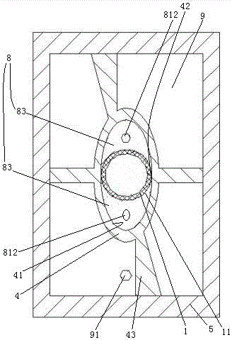
[0035] Embodiment three, see Figure 4 , the difference from Embodiment 1 is: the outer port 813 of the first refrigerant flow channel is located at the part where the outer surface of the anode terminal support seat is located outside the outer tube. The outer port 823 of the second refrigerant flow channel is located at the part where the outer surface of the cathode end support seat is located outside the outer tube.


PUM


Abstract

The invention relates to a laser tube, in particular to a metal laser tube which is not prone to breaking and convenient to manufacture and which is capable of forming a cooling chamber and a gas storage chamber without sintering. The metal laser tube comprises an anode supporting seat provided with an anode channel, a cathode supporting seat provided with a cathode channel, a metal inner tube, a metal outer tube and a glass discharging tube with the anode communicated with the anode channel and cathode channel; two ends of the discharging tube, inner tube and outer tube are connected to the anode and cathode supporting seats respectively in a sealed manner; the inner tube sleeves the discharging tube; the discharging tube, the anode and cathode supporting seats and the inner tube form a cooling chamber provided with two coolant channels; the outer tube sleeves the inner sleeve, the outer tube, the anode and cathode supporting seats and the inner tube form a gas storage chamber, and the anode channel and the cathode channel are communicated with the gas storage chamber. By the aid of the metal laser tube, the problems that a glass-structure laser tube is prone to breaking to cause the loss of a user and is inconvenient to recover and reuse, and large amount of harmful gas is produced during production are solved.

Description

technical field [0001] The invention relates to a laser tube, in particular to a metal laser tube. Background technique [0002] The existing gas laser tubes are all in the form of a sealed structure, that is, including a discharge tube, a water-cooled tube sleeved outside the discharge tube, a gas storage tube sleeved outside the water-cooled tube, electrodes and resonant cavity mirrors (including reflectors and Output mirror), the discharge tube, water cooling tube and gas storage tube are all glass tubes, the water cooling tube and the discharge tube, and the discharge tube and the gas storage tube are all welded together by high-temperature flame firing to form a cooling chamber and a gas storage tube The gas storage chamber communicates with both ends of the discharge tube, and the gas storage chamber is filled with laser gas. [0003] The existing gas laser tubes have the following disadvantages: since the glass tubes are connected together by sintering, a large a...

Claims


Application Information

Patent Timeline
Patent Type & Authority Applications(China)
IPC IPC(8): H01S3/03H01S3/041
Inventor 陈海榕
Owner 陈海榕
Why Eureka
Try Eureka