
Generation method and device of microwave signal with differential phase code

A microwave signal and differential phase technology, applied in the fields of radar, microwave photonics, and communication, can solve the problems of increasing system cost and system complexity, and achieve the effect of increasing power and removing low-frequency background noise interference.

Active Publication Date: 2015-05-20
NANJING UNIV OF AERONAUTICS & ASTRONAUTICS
View PDF3 Cites 23 Cited by
  • Summary
  • Abstract
  • Description
  • Claims
  • Application Information

AI Technical Summary

Problems solved by technology

In recent years, researchers have proposed many methods for generating phase-encoded signals based on microwave photonic technology, but these methods usually have the following problems: First, since the photodetector follows the square-law detection when realizing photoelectric conversion, the obtained phase There are many low-frequency components in the encoded signal, and filters must be used to remove the low-frequency components before the signal is transmitted, which increases the complexity of the system; second, the carrier frequency of the obtained phase-encoded signal is the same as the frequency of the microwave signal source of the drive system , so to generate a high-frequency phase-encoded signal must use a high-frequency microwave signal source, which increases the system cost; third, if a differential phase-encoded microwave signal needs to be generated, the differential encoding of the signal must first be completed in the electrical domain. Then it is used as the input of the microwave photonic system, instead of using the original coded signal as the input to directly generate the differential phase coded microwave signal

Method used


Image

  • Generation method and device of microwave signal with differential phase code
  • Generation method and device of microwave signal with differential phase code
  • Generation method and device of microwave signal with differential phase code

Examples


Embodiment Construction

[0021] The present invention will be further described below in conjunction with the accompanying drawings.

[0022] A microwave signal generation device for differential phase encoding, comprising: a laser, a first electro-optic modulator, a second electro-optic modulator, a cascaded Mach-Zehnder interferometer, a balanced photodetector, a microwave signal source, and a coded signal generator; The output end of the laser is connected to the input end of the first electro-optic modulator; the output end of the first electro-optic modulator is connected to the input end of the second electro-optic modulator; along the signal output direction of the second electro-optic modulator, the cascaded Mach A Zehnder interferometer and a balanced photodetector; the output end of the microwave signal source is connected to the drive signal input end of the first electro-optic modulator; the output end of the coded signal generator is connected to the drive signal input end of the second el...


PUM


Abstract

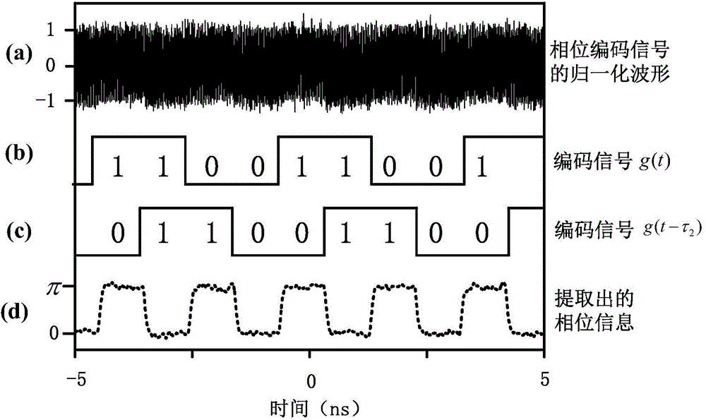
The invention discloses a generation method and device of a microwave signal with a differential phase code, and belongs to the technical field of communication, radar and microwave photonics. The device comprises a laser, a first electro-optical modulator, a second electro-optical modulator, a cascaded Mach-Zehnder interferometer, a balanced photoelectric detector, a microwave signal source and a code signal generator. The method specifically comprises the following steps: performing suppressed carrier modulation on direct current light by using the first electro-optical modulator to obtain two subcarriers; modulating the phase of the code signal on the abovementioned two subcarriers by using the second electro-optical modulator; separating the two subcarriers by using the cascaded Mach-Zehnder interferometer and introducing a proper time delay difference; performing photoelectric detection on two paths of light signals output by the cascaded Mach-Zehnder interferometer by using the balanced photoelectric detector to obtain the microwave signal with the differential phase code. The method and the device have the main advantage that the microwave signal with the differential phase code can be generated, and has the advantages of high carrier frequency, high bandwidth and no low-frequency noise interference.

Description

technical field [0001] The present invention relates to a differential phase encoding microwave signal generation method and device, in particular to a differential phase encoding microwave signal generation method and device based on microwave photon technology, belonging to the fields of communication, radar and microwave photonics. Background technique [0002] Phase encoding or differential phase encoding is a commonly used modulation format in microwave communication systems, and it is also one of the key technologies for realizing pulse compression in radar systems to improve range resolution. In particular, using a differential phase encoding format can significantly improve the reliability of a microwave communication system. As the carrier frequency and bandwidth of phase-encoded signals required by communication and radar systems continue to increase, how to generate high-frequency, large-bandwidth phase-encoded signals has become an urgent problem for communicatio...

Claims


Application Information

Patent Timeline
IPC IPC(8): H04B10/548H04B10/70
Inventor 张方正戈小忠潘时龙
Owner NANJING UNIV OF AERONAUTICS & ASTRONAUTICS
Learn More