Cyclone separator provided with double inlets and double outlets

A technology of cyclone separator and double outlets, which is applied in the direction of swirl devices and devices whose axial direction of swirl can be reversed. In order to improve the separation efficiency, the internal air flow field is uniform and symmetrical, and the longitudinal vortex flow is weakened.

Active Publication Date: 2015-05-27
上海卓旋化工科技有限公司
View PDF8 Cites 5 Cited by
  • Summary
  • Abstract
  • Description
  • Claims
  • Application Information

AI Technical Summary

Problems solved by technology

[0004] At present, there are many types of cyclone separator structures, and most cyclones are not clear in the structure of eliminating the main secondary vortex, so the separation effect on fine particles is not good.
For example, the technical solution of Chinese Patent Publication No. CN2577970Y discloses a cyclone separator, but the internal parts of the cyclone separator are relatively complicated, and have a certain effect on the separation of larger particles, but the structure for eliminating the main secondary eddy current is not clear, so Ineffective for finer particle separation
In addition, for example, the technical solution of Chinese Patent Publication No. CN101422757A discloses a cyclone separator. The cyclone separator adopts the structure of the taper opening at the lower part of the exhaust pipe, which significantly reduces the influence of the upper vortex and affects the fine air. The separation efficiency of particles has been greatly improved, but the influence of longitudinal vortex flow still exists

Method used


Image

  • Cyclone separator provided with double inlets and double outlets
  • Cyclone separator provided with double inlets and double outlets
  • Cyclone separator provided with double inlets and double outlets

Examples


Embodiment Construction

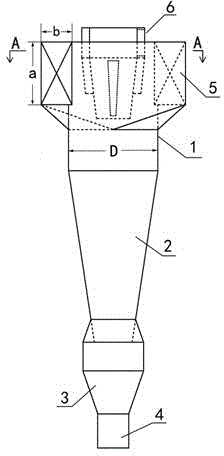
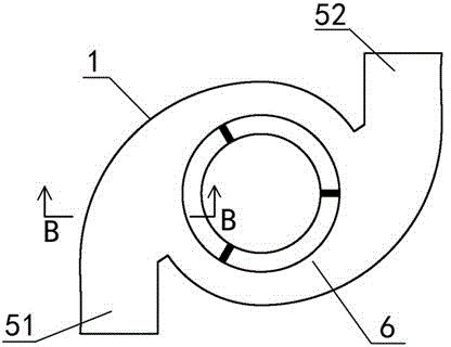
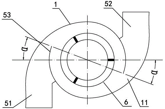
[0025] like figure 1 , figure 2 , image 3 , Figure 4 , Figure 5 and Image 6As shown, this embodiment has a cyclone separator with double inlets and double outlets, including a cyclone body 1, the lower end of the cyclone body 1 is provided with a cone 2, an intermediate ash hopper 3 and a sewage outlet 4 in turn, and the cyclone body 1 The upper end is provided with an air intake assembly 5 and an exhaust assembly 6, and the air intake assembly 5 includes a left air inlet 51 and a right air inlet 52 respectively arranged on the cyclone cylinder 1, and a left air inlet 51 and a right air inlet 52 They are respectively arranged along the tangential direction of the cyclone body 1 and both of them are symmetrically arranged relative to the axis of the cyclone body 1. The arc deflector 53, the air intake of the left air inlet 51 and the right air inlet 52 enters the inside of the cyclone cylinder body 1 after the arc deflector 53 deflects the flow respectively, and the t...


PUM


Abstract

The invention discloses a cyclone separator provided with double inlets and double outlets. The cyclone separator comprises a cyclone barrel body, wherein a cone, a middle ash bucket and a sewage outlet are arranged at the lower end of the cyclone barrel body in sequence; an air inlet component and an air exhausting component are arranged at the upper end of the cyclone barrel body; the air inlet component comprises a left air inlet and a right air inlet, and the left air inlet and the right air inlet are formed in the cyclone barrel body respectively; arc-shaped guiding plates are arranged in the communicating positions that the left air inlet and the right air inlet are communicated with the cyclone barrel body respectively; a gap is reserved between the top of the arc-shaped guiding plates and the cyclone barrel body; the air exhausting component comprises an air exhausting outer pipe, a connecting piece and an air exhausting inner pipe; a plurality of slotted holes uniformly distributed are formed in the side wall of the inner cone-shaped pipe of the air exhausting inner pipe. According to the invention, two main secondary eddy currents of upper eddy current and longitudinal swirling flow existing in cyclone can be effectively eliminated; the cyclone separator has the advantages that the cyclone separator is high in cyclone efficiency, low in cyclone resistance, high in operating flexibility, simple in structure, well-adapted and relatively low in cost, and has a wear-resistant lining.

Description

technical field [0001] The invention belongs to the field of heterogeneous phase separation in chemical engineering, and specifically relates to a device for continuous separation of gas-solid (liquid) mixtures, especially requiring a single unit with large processing capacity, low resistance and high separation efficiency. Cyclone separator with double inlet and double outlet. Background technique [0002] The cyclone separator is a dry gas-solid separation equipment that uses the gas non-uniform system to separate the dust from the air flow by the centrifugal force generated during high-speed rotation. Since the centrifugal force suffered by the particles is far greater than the gravity and inertial force, the minimum particle size that can be economically separated by the cyclone separator can reach 5-10 μm. In addition, the cyclone separator has a relatively simple structure, convenient operation and maintenance, stable performance, and is not limited by the concentrati...

Claims


Application Information

Patent Timeline
Patent Type & Authority Applications(China)
IPC IPC(8): B04C5/00B04C5/04B04C5/081B04C5/14
Inventor 黄晓卫孟祥林黄晓军张丽张丽娟
Owner 上海卓旋化工科技有限公司
Why Eureka
Try Eureka