In-place detection and positioning device for diamond cutting tool

A technology of diamond tools and positioning devices, applied in automatic control devices, precision positioning equipment, manufacturing tools, etc., can solve the problems of in-situ detection, inability to work parameters of tools, time-consuming and labor-intensive, etc.

Inactive Publication Date: 2015-05-27
LASER FUSION RES CENT CHINA ACAD OF ENG PHYSICS
View PDF9 Cites 5 Cited by
  • Summary
  • Abstract
  • Description
  • Claims
  • Application Information

AI Technical Summary

Problems solved by technology

In the domestic ultra-precision cutting process, in addition to the direct introduction of the above-mentioned foreign commercialized tool setting equipment, the self-developed ultra-precision machine tool basically uses the trial cutting method for tool positioning. This method is not only time-consuming and labor-intensive. High, and in-situ detection of tool working parameters cannot be performed

Method used


Image

  • In-place detection and positioning device for diamond cutting tool
  • In-place detection and positioning device for diamond cutting tool
  • In-place detection and positioning device for diamond cutting tool

Examples


Embodiment 1

[0018] This example is figure 1 , figure 2 and image 3 shown.

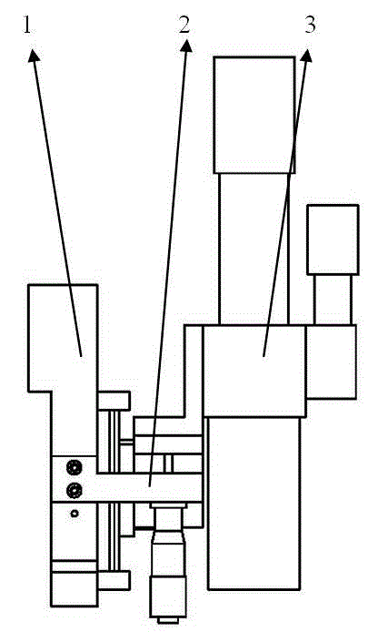
[0019] The diamond cutter in-position detection and positioning device provided by the present invention includes an optical support 1, a fine-tuning and locking mechanism 2, an optical system 3, and an industrial computer. The fine-tuning and locking mechanism 2 is fixedly installed on the optical support 1, and the optical The system 1 is fixedly installed on the adapter plate 24 of the fine adjustment and locking mechanism 2, and moves up and down along the slide rail 23, such as figure 1 shown.

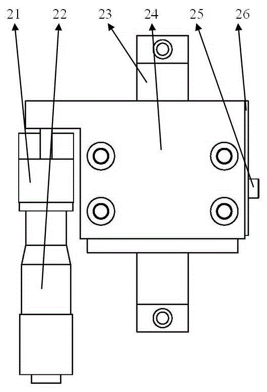
[0020] Described fine-tuning and locking mechanism 2 comprises screw rod fixed frame 21, fine-tuning screw rod 22, slide rail 23, adapter plate 24, locking screw 25, locking piece 26, and its connection relation is, screw rod fixed frame 21, slide rail 23. The locking pieces 26 are all fixedly connected with the optical bracket 1, the optical system 3 is installed on the adapter plate 24 of the fine-tuning and l...

Embodiment 2

[0024] This example is figure 1 shown.

[0025] The in-situ detection and positioning device of the diamond tool as described in Example 1 realizes the in-position detection and positioning of the diamond tool according to the following operation process: 1) The diamond tool is fixedly installed on the tool holder of the ultra-precision machine tool; 2) LVDT electric sensing is used The micrometer adjusts the diamond tool to the calibration position; 3) Move the X and Z guide rails of the ultra-precision lathe, place the diamond tool within the imaging range of the optical system 3, rotate the fine-tuning screw 22 to move the optical system 3 in the vertical direction, and adjust the reflection at the same time Brightness of the light source 32, until a clear image is obtained in the host computer software, tighten the locking screw 25; 5) Move the X guide rail of the ultra-precision machine tool to make the diamond tool move along a straight line within the imaging range, and...

Embodiment 3

[0027] This example is image 3 shown.

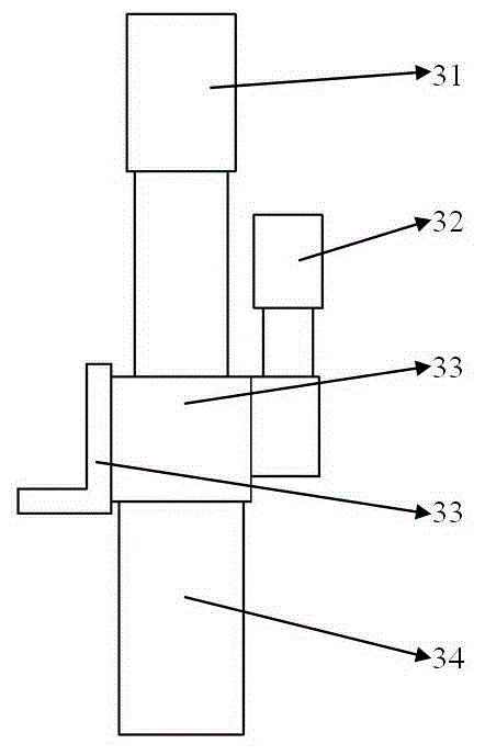
[0028]As in the diamond tool in-position detection and positioning device described in Example 1, the optical system 3 adopts a 5 million-pixel CCD sensor 31, and the lens 34 is a fixed-focus lens with three magnifications of 10 times, 15 times and 20 times, and the reflection light source 32 is a blue LED cold light source, the imaging resolution of the optical system 3 is less than 0.5mm, and the highest resolution can reach 0.16mm according to the different multiples of the lens 34 .

[0029] The diamond cutter in-position detection and positioning device is used to locate the diamond cutter on an ultra-precision machine tool, and the positioning accuracy is better than 1 mm.


PUM


Abstract

The invention provides an in-place detection and positioning device for a diamond cutting tool. The in-place detection and positioning device for the diamond cutting tool comprises an optical bracket, a fine adjustment and locking mechanism, an optical system and an industrial control computer, wherein the fine adjustment and locking mechanism is fixedly arranged on the optical bracket; the optical system is fixedly arranged on an adapter coupling plate of the fine adjustment and locking mechanism, and moves up and down along a sliding rail; the industrial control computer is connected with a CCD (Charge Coupled Device) sensor through a network cable, and is provided with upper computer software for receiving the image data of the CCD sensor and performing data processing. The device can be used for performing in-place detection and positioning on the diamond cutting tool, works independently to detect the diamond cutting tool off line, and is high in system resolution and positioning accuracy, simple in structure and convenient to operate.

Description

technical field [0001] The invention belongs to the field of ultra-precision machining, and in particular relates to a diamond cutter in-position detection and positioning device. Background technique [0002] Diamond tool is an important factor to achieve ultra-precision machining, and the precise determination of its working parameters is a prerequisite for optimizing process parameters and improving machining accuracy. Different from its design parameters, the working parameters of diamond tools must be obtained by in-situ detection on ultra-precision machine tools. In addition, the diamond tool must be accurately installed at the height coincident with the machine tool spindle, and the precise positioning in the horizontal plane can ensure the relative position control of the diamond tool and the machine tool spindle during the machining process, thereby improving the machining accuracy and surface quality. [0003] At present, the LVDT tool setting system is used on fo...

Claims


Application Information

Patent Timeline
Patent Type & Authority Applications(China)
IPC IPC(8): B23Q17/09B23Q17/24B23Q16/00
CPCB23Q17/0904B23Q15/22B23Q17/0919B23Q17/2409B23Q17/2457
Inventor 李国朱瑞童维超黄燕华陶洋刘峰
Owner LASER FUSION RES CENT CHINA ACAD OF ENG PHYSICS
Why Eureka
Try Eureka