Method for reinforcing midspan of ordinary three-span steel continuous beam bridge

A common steel bar and steel bar technology, applied in bridge reinforcement, bridge, bridge maintenance, etc., can solve the problems of lagging stress and strain, failing to reach the design value of tensile strength, and limited improvement of the flexural bearing capacity of the main girder, so as to improve the flexural bearing capacity effect of ability

Active Publication Date: 2015-05-27
广州展亚土木工程技术有限公司
View PDF5 Cites 6 Cited by
  • Summary
  • Abstract
  • Description
  • Claims
  • Application Information

AI Technical Summary

Problems solved by technology

The disadvantage of this form of reinforcement is that the steel plate cannot participate in bearing the constant load bending moment that has acted on the main beam before reinforcement, but can only participate in bearing the bending moment caused by the vehicle load, and the flexural bearing capacity of the main beam after strengthening is limited; the steel plate Compared with the existing tensile reinforcement of the main girder, its stress and strain lag relatively behind. In the limit state, its stress and strain are far below the design value of the tensile strength, but the mid-span tensile reinforcement of the main girder has reached its tensile strength. Design strength, resulting in the inability to give full play to the material properties of the steel plate

Method used


Image

  • Method for reinforcing midspan of ordinary three-span steel continuous beam bridge
  • Method for reinforcing midspan of ordinary three-span steel continuous beam bridge
  • Method for reinforcing midspan of ordinary three-span steel continuous beam bridge

Examples


Embodiment Construction

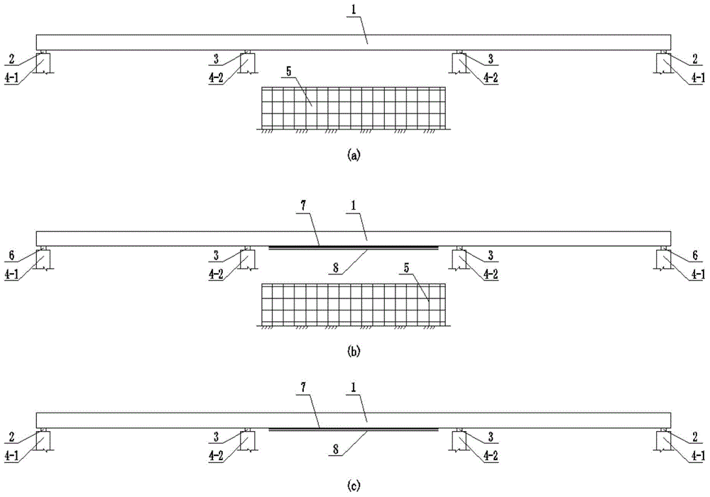
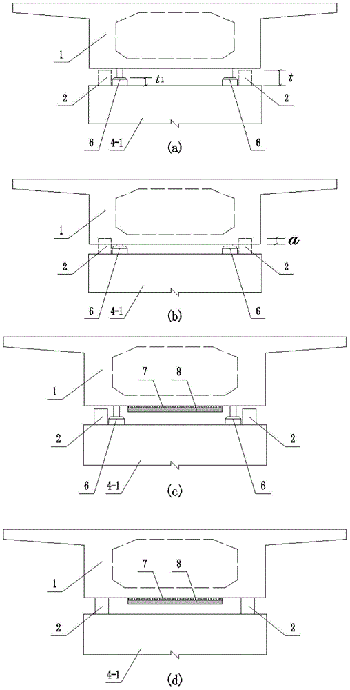
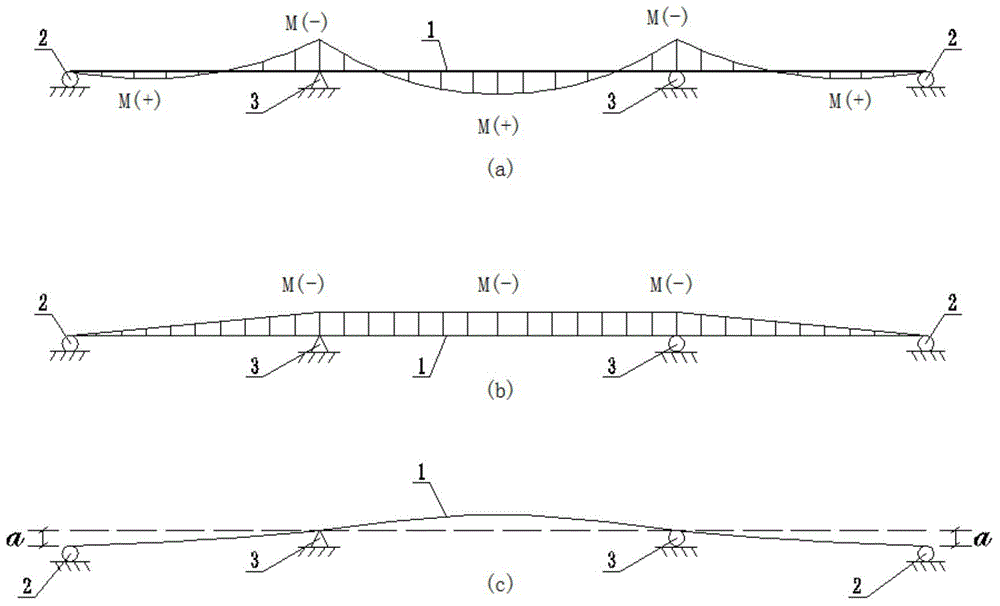
[0052] The present invention will be further described below in conjunction with drawings and embodiments.

[0053] This embodiment is to strengthen the middle span of a certain three-span ordinary reinforced concrete continuous girder bridge, such as figure 1 As shown in the figure, the side-span support 2 is placed on the side-span pier 4-1, the mid-span support 3 is placed on the mid-span pier 4-2, and the main girder 1 is composed of the side-span support 2 and the mid-span support 3 Support, the span combination of the continuous girder bridge is (14+20+14)m, the main girder 1 is made of C40 concrete, the section is box-shaped, the section height is 1.4m, the roof width is 8.5m, the average thickness of the roof is 22.5cm, and the width of the bottom plate is 4.5m m; the height of the side-span support 2 and mid-span support 3 is 350mm, and the upper edge of the main beam at the mid-span support is equipped with 68 φ28HRB335 longitudinal tensile steel bars, and the effect...


PUM


Abstract

The invention discloses a method for reinforcing a midspan of an ordinary three-span steel continuous beam bridge. The method comprises the following steps: building a construction operation platform; treating the surface of a midspan bottom plate; jacking up two side spans by virtue of a jack and then dismantling a side span support seat; lowering the jack to be lower than the side span support seat; calculating to obtain the lowered value of the jack relative to the side span support seat; unloading dead load bending moment of the midspan, and then pasting and fixing with a steel plate; jacking up the edge spans by virtue of the jack, and reinstalling the dismantled side span support seat at the original position; and lowering the jack, relocating the edge spans on the side span support seat, and then shifting out the jack. According to the method, by unloading the dead load bending moment of the midspan and then pasting and fixing with the steel plate, the steel plate can participate into the activities of bearing the load of a car and then adding dead load, can also participate into the activity of bearing the dismantled dead load bending moment; the bending bearing capacity of the main girder can be effectively improved; meanwhile, the material properties of reinforcing steel plate can be put into a relatively full play; and the bridge safety is not affected by lowering the jack in the construction process.

Description

technical field [0001] The invention relates to highway bridges, in particular to a method for reinforcing the mid-span of a three-span common reinforced continuous girder bridge through constant-load bending moment unloading and pasting steel plates. Background technique [0002] Ordinary reinforced continuous girder bridge is a type of bridge commonly used in small and medium span bridges. It has the advantages of less joints, good rigidity, smooth and comfortable driving, etc. It is often the bridge type scheme selected within the span of (15-30)m The winners, mostly dominated by concrete box sections. Three-span ordinary reinforced continuous girder bridge is a relatively common bridge span combination. Generally, the span of the middle span is larger than that of the two side spans. The main control position of bridge design is also the position that is more prone to problems in the actual operation of the bridge. The mid-span bending moment of the mid-span is an impo...

Claims


Application Information

Patent Timeline
Patent Type & Authority Applications(China)
IPC IPC(8): E01D22/00
CPCE01D22/00
Inventor 薛兴伟张敏江张海王泽成
Owner 广州展亚土木工程技术有限公司
Why Eureka
Try Eureka