Single-row time-grating linear displacement sensor based on tectonic movement optical field
A technology of structural motion and linear displacement, applied in the field of sensors, can solve the problems of difficult phase, measurement error, consistency, etc., to reduce the difficulty of installation and processing technology, simplify the system structure, and reduce the effect of measurement error
- Summary
- Abstract
- Description
- Claims
- Application Information
AI Technical Summary
Problems solved by technology
Method used
Image

Examples
Embodiment 1
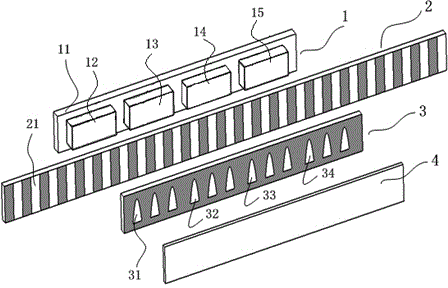
[0027] Embodiment 1: as Figure 1 to Figure 5 The shown single-row time grating linear displacement sensor based on the construction of a moving light field includes a light-emitting element 1, a fixed-scale substrate 2, a moving-scale substrate 3 and a photodetector 4, and a light-emitting element 1, a moving-scale substrate 3 and a photodetector 4 Move at the same time, and the fixed-length substrate 1 is fixed.
[0028] Light-emitting element 1 is installed in the rear of fixed-length base body 2, and light-emitting element 1 is made of light source base body 11 and four light source bodies (i.e. first light source body 12, second light source body 13, third light source body 14 and The fourth light source body 15) is arranged at intervals along the measuring direction (ie, the length direction of the light source base body); The first light source body 12 is driven by a sinusoidal excitation electric signal with a phase of 0°, and the second light source body 13 is driven...
Embodiment 2
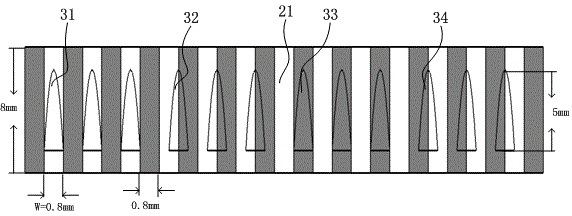
[0041] Embodiment 2: as Figure 6 , Figure 7 The shown single-row time grating linear displacement sensor based on the construction of a moving light field, most of its structure and measurement principle are the same as in Embodiment 1, the difference is that: the light emitting element 1 is composed of a light source substrate 11 and an equal-sized and non-interfering light source. Three light source bodies (i.e. the first light source body 12, the second light source body 13 and the third light source body 14) are arranged at intervals along the measuring direction; the first light source body 12, the second light source body 13 and the third light source body 14 are all Using a strip-shaped semiconductor surface light source, the first light source body 12 is driven by a sinusoidal excitation electrical signal with a phase of 0°, and the second light source body 13 is driven by a sinusoidal excitation electrical signal with the same frequency and amplitude as the aforemen...
Embodiment 3
[0052] Embodiment 3: as Figure 8 , Figure 9 The shown single-row time grating linear displacement sensor based on the construction of a moving light field, most of its structure and measurement principle are the same as in Embodiment 1, the difference is that: the light emitting element 1 is composed of a light source substrate 11 and an equal-sized and non-interfering light source. Six light source bodies (i.e. the first light source body 12, the second light source body 13, the third light source body 14, the fourth light source body 15, the fifth light source body 16, and the sixth light source body 17) are arranged at intervals along the measurement direction; The first light source body 12, the second light source body 13, the third light source body 14, the fourth light source body 15, the fifth light source body 16, and the sixth light source body 17 all adopt strip-shaped semiconductor surface light sources. It is driven by a sinusoidal excitation electric signal wi...
PUM
 Abstract
Description
Claims
Application Information
 - R&D
- Intellectual Property
- Life Sciences
- Materials
- Tech Scout
- Unparalleled Data Quality
- Higher Quality Content
- 60% Fewer Hallucinations
Browse by: Latest US Patents, China's latest patents, Technical Efficacy Thesaurus, Application Domain, Technology Topic, Popular Technical Reports.
© 2025 PatSnap. All rights reserved.Legal|Privacy policy|Modern Slavery Act Transparency Statement|Sitemap|About US| Contact US: help@patsnap.com