Battery module

A technology for battery modules and battery cells, applied in the direction of secondary batteries, circuits, electrical components, etc., can solve the problems of small heat transfer area, safety risks of cooling systems, and increased equipment costs, and achieve the effect of large area

Active Publication Date: 2015-05-27
ROBERT BOSCH GMBH
View PDF4 Cites 2 Cited by
  • Summary
  • Abstract
  • Description
  • Claims
  • Application Information

AI Technical Summary

Problems solved by technology

The disadvantage here is that the equipment costs for providing the components required for cooling are increased and, moreover, the area via which heat is transferred from the battery cells to the fluid-flowing plates is relatively small.
Furthermore, safety risks due to leaks in the cooling system

Method used


Image

  • Battery module
  • Battery module
  • Battery module

Examples


Embodiment Construction

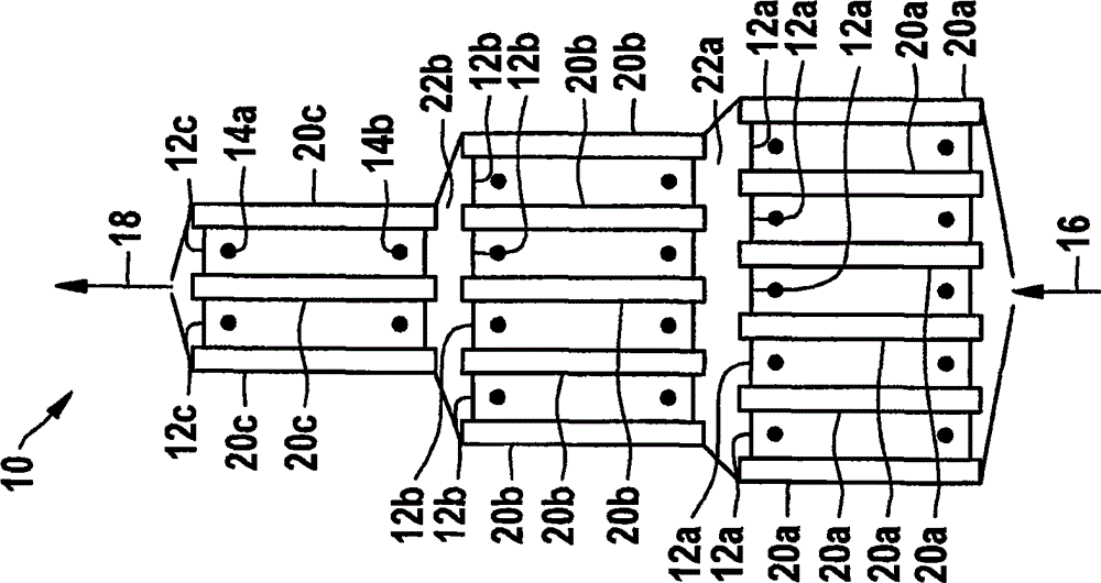
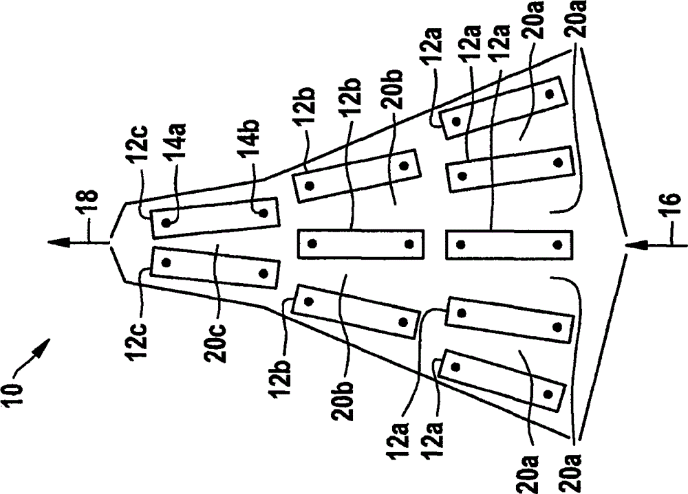
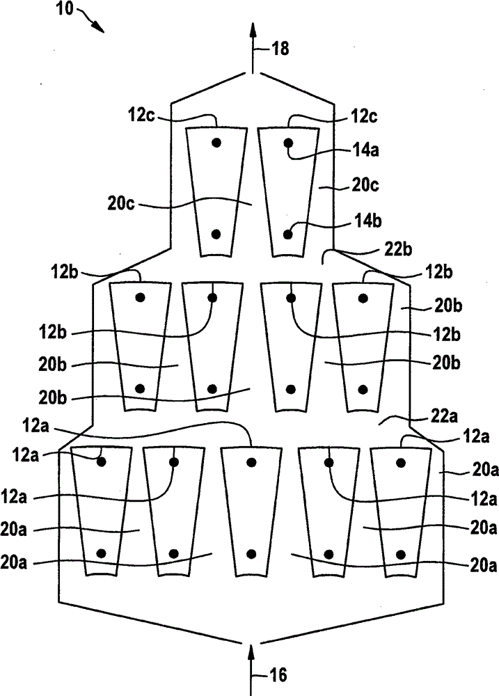
[0025] exist figure 1 A battery module 10 is depicted in , which for example comprises a plurality of battery cells 12a, 12b, 12c. The battery cells 12a, 12b, 12c each have two battery terminals 14a, 14b via which the battery cells 12a, 12b, 12c are electrically contacted. The battery cells 12 a , 12 b , 12 c are present, for example, in a cylindrical embodiment, in a prismatic embodiment or as so-called pouch-cells (batteries in pockets). In addition, the battery cells 12 a , 12 b , 12 c are connected in parallel or in series with each other in a suitable manner in the battery module 10 . Since heat is released both during charging and discharging and the corresponding battery cells 12a, 12b, 12c should be operated in a defined temperature window in order not to compromise their durability, the battery cells of the battery module 10 The individual cells 12a, 12b, 12c are temperature controlled in a suitable manner.

[0026] The concept of temperature control here includes ...


PUM


Abstract

Described is a battery module (10), in particular a lithium-ion battery, lithium-sulfur battery, or lithium-air battery. The battery module is provided with a plurality of battery cells (12a, 12b, 12c) and has an inlet for a cooling medium (16 ) as well as an outlet for the cooling medium (18), wherein the cooling medium at least partially flowing around the outer sides of the battery cells (12a, 12b, 12c) and the total flowing cross section, formed by the space (20a, 20b, 20c) between battery cells (12a, 12b, 12c), of the cooling medium is decreased in the flowing direction of the cooling medium.

Description

technical field [0001] The invention relates to a battery module and its use according to the preambles of the independent claims. Background technique [0002] Batteries with high electrical power output capacity are gaining more and more importance. A new generation of batteries is implemented in the form of so-called lithium-ion batteries. It is important here that, in order to ensure the safety and function of such a battery pack, the individual battery cells contained in the battery pack are operated within a predetermined temperature range. Waste heat in the form of Joule heat is thus already formed only during the operation of the corresponding battery cell, which is formed due to the current flowing in the battery cell and the internal resistance of the battery cell, and also due to the reversible chemistry in the battery cell The process also forms heat. The heat formed is dissipated from the battery cells in order to avoid heating of the battery cells above a cr...

Claims


Application Information

Patent Timeline
IPC IPC(8): H01M10/613H01M10/617H01M10/6557
CPCH01M10/613H01M10/625H01M10/6557H01M10/6561H01M10/6566Y02E60/10
Inventor A·施密特L·洛伦茨
Owner ROBERT BOSCH GMBH
Why Eureka
Try Eureka