Supercharge Your Innovation With Domain-Expert AI Agents!

Switch reluctance wind driven generator control system and method

A wind turbine and switched reluctance technology, applied in the control system, controlling the generator through the change of the magnetic field, controlling the generator, etc., can solve the problem of low power quality, increased daily maintenance costs, and large fluctuations in the generator voltage and current and other problems, to achieve the effect of low manual participation, improved power generation efficiency, and stable power generation voltage

Inactive Publication Date: 2015-05-27
CHINA JILIANG UNIV
View PDF6 Cites 18 Cited by
  • Summary
  • Abstract
  • Description
  • Claims
  • Application Information

AI Technical Summary

Problems solved by technology

[0003] From the perspective of excitation mode, switched reluctance generators are classified into two types: self-excitation and self-excitation. The output voltage of the self-excitation mode has relatively small fluctuations and is relatively stable, but it relies on an external special DC power supply, which increases the cost of daily maintenance; self-excitation. In the excitation mode, the excitation power comes from the output terminal of the generator voltage, but in the traditional self-excitation mode, due to the coupling of the excitation power and the generator power supply, and the fact that the excitation current fluctuates from time to time when the generator is running, it also affects the output of the generator. Power generation voltage and current fluctuate greatly, and power quality is low

Method used


Image

  • Switch reluctance wind driven generator control system and method
  • Switch reluctance wind driven generator control system and method

Examples


Embodiment Construction

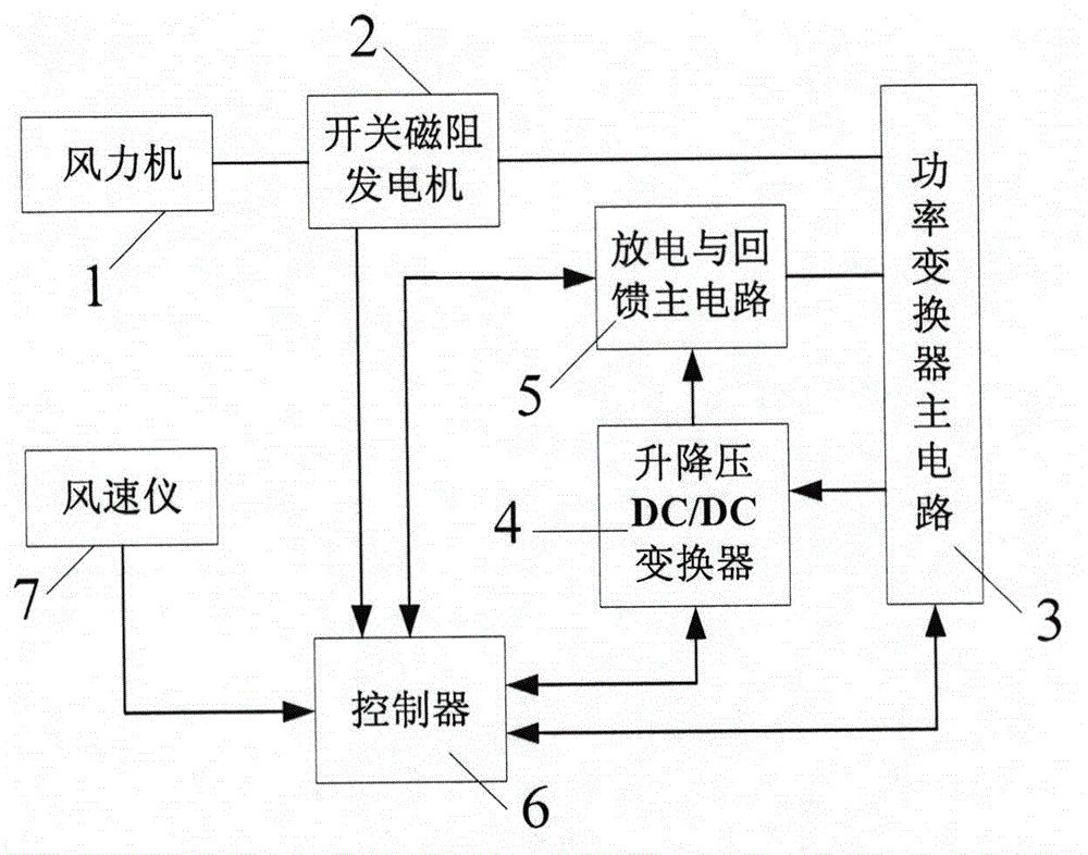
[0038] figure 1 It is a structural diagram of the switched reluctance wind generator system of the present invention. The wind turbine 1 is a variable-pitch variable-speed wind turbine. The wind turbine 1 is equipped with a speed increaser. The switched reluctance generator 2 of the embodiment is a four-phase winding (respectively as figure 2 Shown A, B, C, D), the power converter main circuit 3 is connected to each phase winding in the switched reluctance generator 2; the controller 6 uses a high-speed DSP as the core processor, and it receives the wind speed signal of the anemometer 7 , the rotor position and speed signals of the switched reluctance generator 2, the current signals of each phase winding branch of the switched reluctance generator 2 in the main circuit 3 of the power converter, the bus current, the output power generation voltage signal, and the buck-boost DC The output voltage signal of the / DC converter 4, the voltage signal of the energy storage capacito...


PUM


Abstract

The invention relates to a switch reluctance wind driven generator control system and method. The control system comprises a wind machine, a switch reluctance generator, a power converter main circuit, a boost-buck DC / DC converter, a discharging and feedback main circuit, a controller and an anemograph, wherein the wind machine is connected with the switch reluctance generator, the switch reluctance generator is connected with the power converter main circuit and is controlled by the power converter main circuit, the output of the power converter main circuit is connected with the boost-buck DC / DC converter and the discharging and feedback main circuit, and the output of the power converter main circuit is connected with the discharging and feedback main circuit, and the controller is connected to all components except for the wind machine. According to the control method, exciting voltage and generating voltage are decoupled based on a self-excitation manner, the enough exciting voltage is guaranteed by virtue of a boost-buck chopper circuit in a low speed operation process of a generating system, the generating system can absorb excess electric energy and enters an excitation link in a high speed operation process, and the stability of the generating voltage is maintained. According to the control system and method, the generating range can be expanded, and the generating efficiency and benefit can be increased.

Description

technical field [0001] The invention relates to the field of wind power generation, in particular to a switched reluctance generator as a control device and a control method for a wind power generator. Background technique [0002] As a wind power generator, the switched reluctance generator has been involved at home and abroad. [0003] From the perspective of excitation mode, switched reluctance generators are classified into two types: self-excitation and self-excitation. The output voltage of the self-excitation mode has relatively small fluctuations and is relatively stable, but it relies on an external special DC power supply, which increases the cost of daily maintenance; self-excitation. In the excitation mode, the excitation power comes from the output terminal of the generator voltage, but in the traditional self-excitation mode, due to the coupling of the excitation power and the generator power supply, and the fact that the excitation current fluctuates from time...

Claims


Application Information

Patent Timeline
IPC IPC(8): H02P9/14H02P9/30H02P101/15
CPCH02P9/14H02P9/30
Inventor 孙冠群
Owner CHINA JILIANG UNIV
Features
  • R&D
  • Intellectual Property
  • Life Sciences
  • Materials
  • Tech Scout
  • Unparalleled Data Quality
  • Higher Quality Content
  • 60% Fewer Hallucinations
Learn More