
A method and device for realizing optical signal delay by using fluorescence effect

A fluorescent signal and optical signal technology, applied in the field of optical signal regulation, can solve the problems of high cost, complex method, large space occupation, etc., and achieve the effect of convenient operation and simple equipment

Inactive Publication Date: 2017-11-07
FUJIAN NORMAL UNIV
View PDF7 Cites 0 Cited by
  • Summary
  • Abstract
  • Description
  • Claims
  • Application Information

AI Technical Summary

Problems solved by technology

However, this delay technology mainly has the following disadvantages: 1) The delay time is usually fixed and cannot be adjusted flexibly
2) Due to the increase of the optical path, the attenuation of the signal is serious, which is not conducive to signal transmission
3) It requires a lot of materials, takes up a lot of space, is expensive, and is not easy to maintain
However, the methods of these routing technologies are complicated, the control is difficult, and the delay effect can only be realized in the transmission direction of the signal, and the delayed signal cannot be flexibly extracted to realize the effective use of the delayed signal

Method used


Image

  • A method and device for realizing optical signal delay by using fluorescence effect
  • A method and device for realizing optical signal delay by using fluorescence effect

Examples


Embodiment Construction

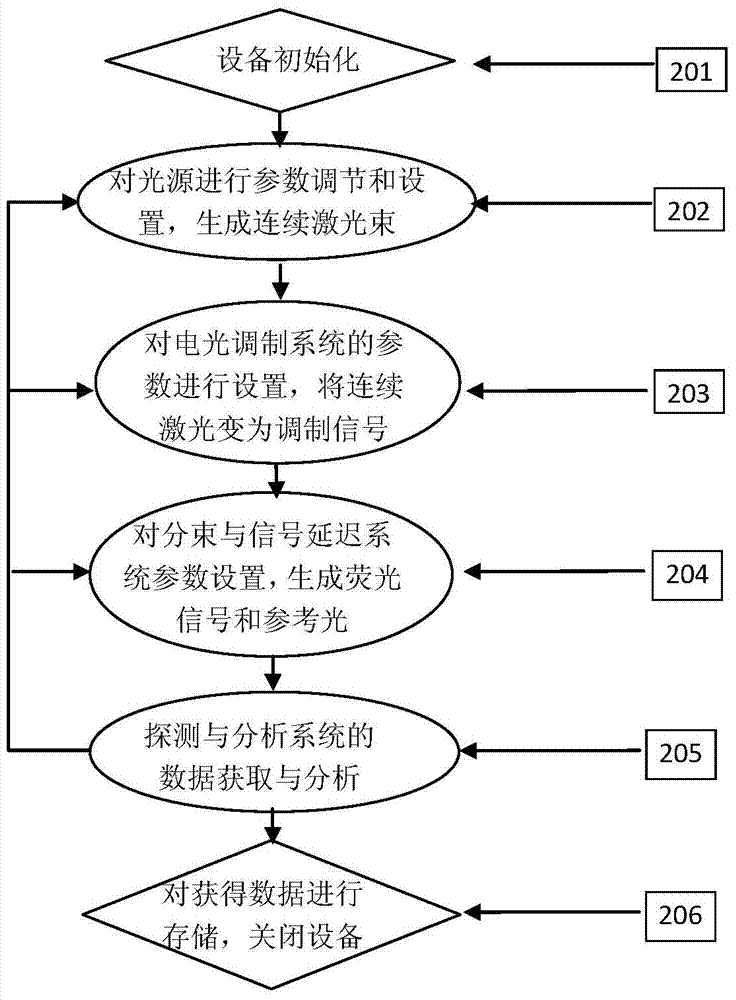
[0024] Such as figure 1 As shown, a device of the present invention that utilizes the fluorescence effect to realize optical signal delay includes sequentially connected light sources, electro-optical modulation systems, beam splitting and signal delay systems, and detection and analysis systems;

[0025] The light source generates continuous laser light; the light source is a laser, and the wavelength of the continuous laser light is 532nm.

[0026] Described electro-optic modulation system is made up of polarizer, electro-optic crystal, analyzer and signal source; Polarizer changes the continuous laser light from light source into linearly polarized light; Change its polarization state; the analyzer converts the polarized light from the electro-optic crystal into linearly polarized light whose polarization direction is perpendicular to the polarization direction of the polarizer to complete the modulation process to generate a modulation signal; the electro-optic crystal and...


PUM


Abstract

The invention relates to the field of optical signal regulation, in particular to a method and device for realizing optical signal delay by using fluorescence effect. The device of the present invention comprises a sequentially connected light source, electro-optic modulation system, beam splitting and signal delay system, and a detection and analysis system; the light source generates continuous laser light, the electro-optic modulation system sinusoidally modulates the continuous laser light into a modulation signal, and the beam splitting and signal delay system The modulation signal is divided into signal light and reference light, and the signal light enters the ruby ​​crystal to excite the fluorescent signal, which has an obvious time delay and retains the modulation information of the signal light; the detection and analysis system detects the fluorescent signal and reference light, and calculates The time delay of the fluorescent signal relative to the reference light. The invention solves the shortcomings of the traditional optical delay system and does not need complex equipment and control methods. The device of the invention is simple and easy to operate, and can realize the reception and utilization of delayed signals in any direction in space.

Description

technical field [0001] The invention relates to the field of optical signal regulation, in particular to a method and device for realizing optical signal delay by using fluorescence effect. Background technique [0002] In recent years, optical communication has been widely used because of its advantages of low cost and high performance. One of the cores of optical communication technology is the routing of optical signals, that is, the delay control technology of signals. The traditional optical signal routing technology is mainly realized by increasing the optical distance, for example, using fiber optic coils. However, this delay technology has the following disadvantages: 1) The delay time is usually fixed and cannot be adjusted flexibly. 2) Due to the increase of the optical distance, the attenuation of the signal is serious, which is not conducive to signal transmission. 3) It requires a lot of materials, takes up a lot of space, is expensive, and is not easy to mai...

Claims


Application Information

Patent Timeline
Patent Type & Authority Patents(China)
IPC IPC(8): H04B10/27
Inventor 张春光王号
Owner FUJIAN NORMAL UNIV
Learn More