Surface machining method for obtrusive hollow cylinder and ball end mill

A processing method, hollow cylinder technology, applied in the direction of milling cutters, metal processing equipment, milling machine equipment, etc., can solve problems such as time delay, affecting processing accuracy, reducing tool rigidity, etc., to reduce production costs, reduce clamping times, and ensure The effect of processing quality

Inactive Publication Date: 2015-06-03
TIANJIN UNIV OF COMMERCE
View PDF11 Cites 5 Cited by
  • Summary
  • Abstract
  • Description
  • Claims
  • Application Information

AI Technical Summary

Problems solved by technology

The reason is that the thin-walled parts have poor rigidity and weak strength. During the processing, they are deformed due to the influence of clamping force, heat, vibration and other factors, which makes it more difficult to guarantee the processing accuracy of the workpiece.
Especially when precision machining of light thin-walled aluminum plate workpieces with extended hollow cylindrical surfaces, the machining stability is very poor
Since the top of the cylindrical shell has an outstretched ring, it is processed by an ordinary three-axis vertical machine tool. Since the general-purpose ball milling tool cannot extend to the position blocked by the ring, usually this part needs to be installed three times. The processing can only be completed by clamping, which not only delays time but also affects the processing accuracy
If more high-end four-axis or five-axis machine tools are used for processing, although the number of clamping times can be reduced, it is difficult for ordinary enterprises to bear the high cost of using high-end machine tools to process parts.
[0004] At the same time, since the diameter of the cutter shaft of the general-purpose ball milling cutter is the same as the diameter of the ball head, the cutter cannot extend to the surface of the circular table blocked by the protruding ring during processing, and three additional installations are required.
When processing the curved surface of the circular table for the last time, the workpiece needs to be erected for clamping. The schematic diagram of the clamping is as follows Figure 5 As shown, the length of the tool required in this scheme is large, and the rigidity during tool processing is reduced due to the large length of the tool

Method used


Image

  • Surface machining method for obtrusive hollow cylinder and ball end mill
  • Surface machining method for obtrusive hollow cylinder and ball end mill
  • Surface machining method for obtrusive hollow cylinder and ball end mill

Examples


Embodiment Construction

[0027] The present invention will be described in further detail below in conjunction with the accompanying drawings and specific embodiments.

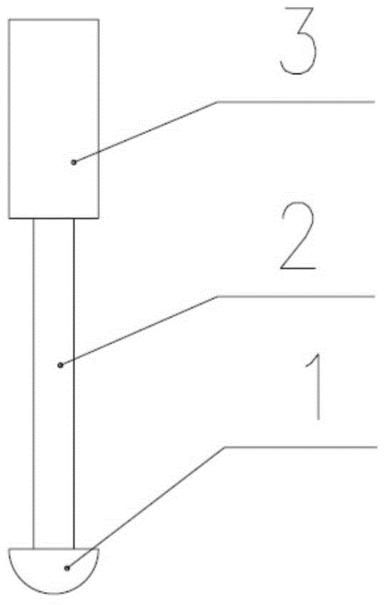
[0028] The processing method of the present invention adopts a special ball milling cutter, and its schematic diagram is as follows: figure 1 As shown, it includes the cutter bar clamping part 3, the cutter bar 2 and the ball head 1, the diameter of the cutter bar 2 is smaller than the diameter of the ball head 1, and the difference between the diameter of the cutter bar 2 and the ball head 1 It is larger than the width of the protruding ring of the workpiece being processed. The ball head 1 is in the shape of a semicircular drum.

[0029] Hereinafter, a specific workpiece is taken as an example to describe in detail.

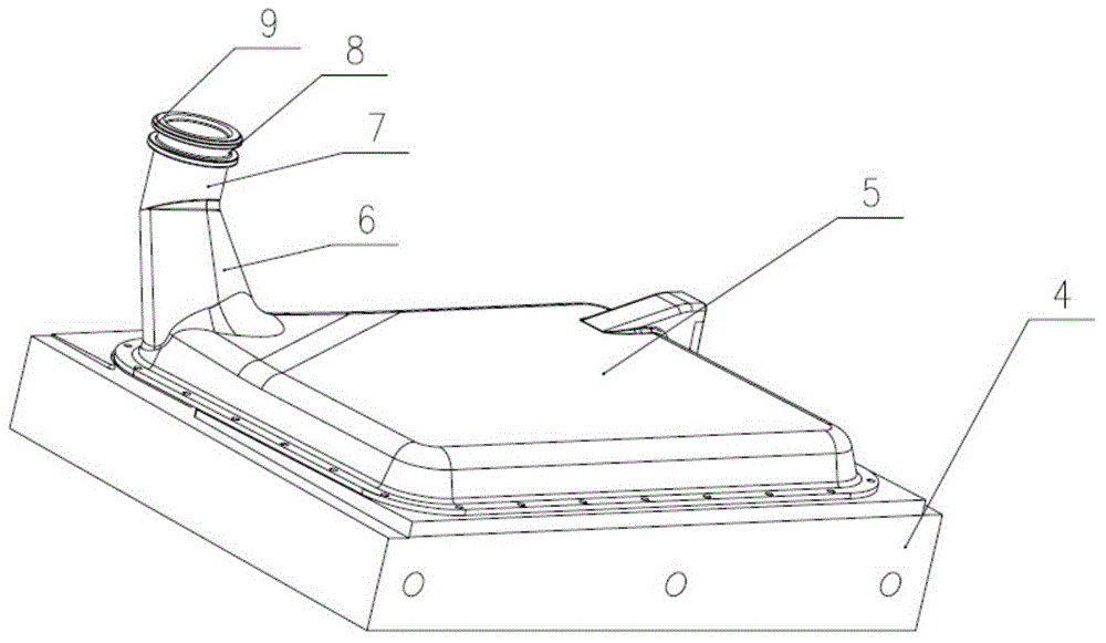
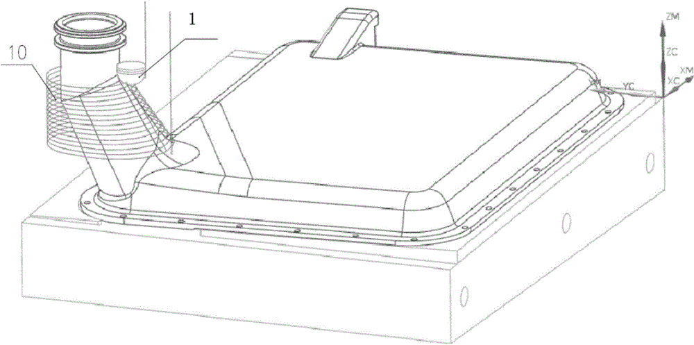
[0030] The workpiece 5 of the present embodiment has a protruding hollow cylindrical curved surface, and its schematic diagram is as follows Figure 4 As shown, its dimensions are as follows, the total height of th...


PUM


Abstract

The invention discloses a surface machining method for an obtrusive hollow cylinder and a ball end mill, in particular to the machining method and the ball end mill which use an ordinary three-shaft vertical machine, and can reduce clamping frequency, improve machining efficiency and machining stability. The machining method comprises course machining and fine machining, wherein the fine machining comprises the following steps: 1, semifinishing a round groove, a cylindrical face and a circular truncated cone curved face by a T-shaped milling cutter, wherein the unilateral margins of the round groove and the cylindrical face are both 0.15 mm, and the machining margin of the circular truncated cone curved face is 0.12 mm; 2, finishing the round groove, the cylindrical face and the circular truncated cone curved face by the T-shaped milling cutter, wherein the parameters of the T-shaped milling cutter are the same as the parameters in step 1, the margins for machining the round groove and the cylindrical face are 0 mm, namely, machining is in place, and the unilateral margin of the circular truncated cone curved face is 0.08 mm; 3, finishing the circular truncated cone curved face by adopting the specially made ball end mill, wherein the smallest cutting length is 0.1 mm. For the specially made ball end mill, the diameter of the cutter bar is smaller than that of the bulb. The machining quality of a part is ensured by the method and use of the ball end mill.

Description

technical field [0001] The invention relates to the technical field of mechanical processing, and more specifically, relates to a method for processing the curved surface of an overhanging hollow cylinder and a special ball milling cutter used in the processing process. Background technique [0002] Thin-walled workpieces are widely used in various industrial fields because of their light weight, low cost and compact structure. [0003] At present, the processing of thin-walled parts has always been a problem that plagues the machining industry. The reason is that the thin-walled parts have poor rigidity and weak strength. During the processing, they are deformed due to the influence of clamping force, heat, vibration and other factors, which makes it more difficult to guarantee the processing accuracy of the workpiece. Especially when the precision machining of light-duty thin-walled aluminum plate workpieces with extended hollow cylindrical surfaces, the processing stabil...

Claims


Application Information

Patent Timeline
Patent Type & Authority Applications(China)
IPC IPC(8): B23C3/00B23C5/12
CPCB23C3/00B23C5/12
Inventor 王勇洪林李丽军邓江郭瑞齐颖眉张万丰刘云龙郑维何俊波
Owner TIANJIN UNIV OF COMMERCE
Why Eureka
Try Eureka