Movement mechanism of spot welding machine PCB (printed circuit board)

A motion mechanism and PCB board technology, applied in PCB positioning, welding equipment, circuit board tool positioning and other directions during processing, can solve problems affecting mounting components, etc., meet production needs, facilitate popularization and use, and have a novel and reasonable design Effect

Inactive Publication Date: 2015-06-03
SHAANXI ZIZHU ELECTRON
View PDF0 Cites 4 Cited by
  • Summary
  • Abstract
  • Description
  • Claims
  • Application Information

AI Technical Summary

Problems solved by technology

[0002] With the development of electronic products, according to the requirements of various functions, the requirements for the soldering position of the components on the PCB are getting higher and higher. There are all through-hole plug-in PCBs, all patch PCBs, and plug-in mixed PCBs. The process is that all through-hole plug-in PCBs are welded with a spot welder; all patch PCBs are welded with a reflow soldering machine; there are two types of plug-in mixed PCBs, and the plug-in mixed components are on the same side of the PCB first with a reflow soldering machine Solder the mounted components, and then use the spot welding machine to weld the plug-in components; if the plug-in mixed components are not on the same side of the PCB, first use the reflow soldering machine to weld the mounted components, and then manually weld the plug-in components, because if you use a spot welder Machine soldered plug-in components will affect soldered mounted components

Method used


Image

  • Movement mechanism of spot welding machine PCB (printed circuit board)
  • Movement mechanism of spot welding machine PCB (printed circuit board)
  • Movement mechanism of spot welding machine PCB (printed circuit board)

Examples


Embodiment Construction

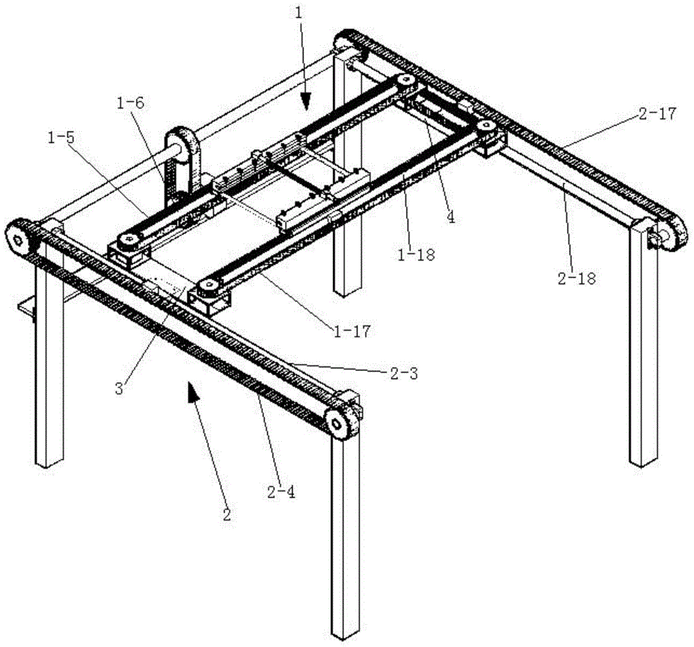
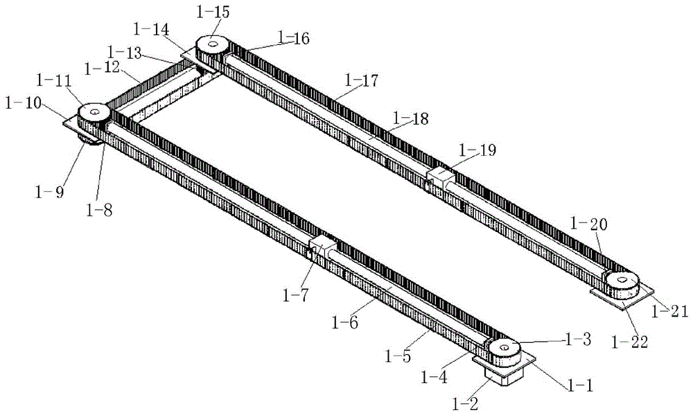
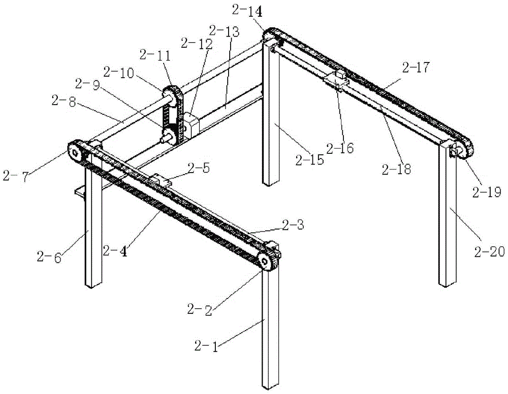
[0036] Such as figure 1 , figure 2 and image 3The movement mechanism of a spot welding machine PCB board shown includes a Y-axis movement mechanism 2 and an X-axis movement mechanism 1 installed on the Y-axis movement mechanism 2; the X-axis movement mechanism 1 includes a horizontally arranged driving belt 1 -5, driven belt 1-17, the first driving pulley 1-3 and the second driving pulley 1-11 for driving the driving belt 1-5, and the first driven for driving the driven belt 1-17 Pulley 1-15 and the second driven pulley 1-21; said driving belt 1-5 is parallel to driven belt 1-17, and a transmission is arranged between said driving belt 1-5 and driven belt 1-17 Belt 1-12, a drive motor 1-2 is arranged below the first drive pulley 1-3, and the central axis of the first drive pulley 1-3 is rotated and installed between the drive motor 1-2 and the first drive pulley 1 -3 on the first mount 1-1, the drive motor 1-2 is installed on the first mount 1-1, the output shaft of the d...


PUM


Abstract

The invention discloses a movement mechanism of a spot welding machine PCB (printed circuit board). The movement mechanism comprises a Y-axis movement mechanism and an X-axis movement mechanism, the X-axis movement mechanism comprises a driving belt, a driven belt, a first driving belt pulley, a second driving belt pulley, a first driven belt pulley, a second driven belt pulley, a first guide rod and a second guide rod, a first slider is mounted on the first guide rod, one side face of the first slider is connected with the driving belt, a second slider is mounted on the second guide rod and is in sliding fit with the second guide rod, and one side face of the second slider is connected with the driven belt. The Y-axis movement mechanism comprises a first driven transmission belt, a second driven transmission belt, a first sliding rod and a second sliding rod, a first moving block is mounted on the first sliding rod and connected with the first driven transmission belt, and a second moving block is mounted on the second sliding rod and connected with the second driven transmission belt. The movement mechanism of the spot welding machine PCB can drive the PCB to do combined motion of an X-axis direction and a Y-axis direction.

Description

technical field [0001] The invention relates to a movement mechanism, in particular to a movement mechanism of a PCB board of a spot welding machine. Background technique [0002] With the development of electronic products, according to the requirements of various functions, the requirements for the soldering position of the components on the PCB are getting higher and higher. There are all through-hole plug-in PCBs, all patch PCBs, and plug-in mixed PCBs. The process is that all through-hole plug-in PCBs are welded with a spot welder; all patch PCBs are welded with a reflow soldering machine; there are two types of plug-in mixed PCBs, and the plug-in mixed components are on the same side of the PCB first with a reflow soldering machine Solder the mounted components, and then use the spot welding machine to weld the plug-in components; if the plug-in mixed components are not on the same side of the PCB, first use the reflow soldering machine to weld the mounted components, ...

Claims


Application Information

Patent Timeline
Patent Type & Authority Applications(China)
IPC IPC(8): B23K3/08H05K3/34
CPCB23K3/08B23K2101/42H05K3/0008H05K3/34H05K2203/15
Inventor 蒲维新
Owner SHAANXI ZIZHU ELECTRON
Why Eureka
Try Eureka