Eureka AIR delivers breakthrough ideas for toughest innovation challenges, trusted by R&D personnel around the world.

Gas valves for different gas sources

A gas valve and gas source technology, applied in the direction of valve devices, cocks including cut-off devices, engine components, etc., can solve the problems of inconvenient installation and maintenance of valve cores, reduced service life of gas valves, complex adjustable structure of valve cores, etc. , to achieve the effect of ensuring strength, reducing production and assembly costs, and requiring high processing accuracy

Active Publication Date: 2017-01-18
广东金尚智能电气有限公司
View PDF8 Cites 0 Cited by
  • Summary
  • Abstract
  • Description
  • Claims
  • Application Information

AI Technical Summary

Problems solved by technology

However, the patented spool adjustable structure is relatively complicated. It processes a threaded blind hole on the inner spool to screw the upper limit pin and at least two flow limit holes. It needs to mill a long arc on the outer spool. Shaped slot for the limit pin installed on the inner valve core to fall into the slot, when the inner valve core is rotated to make the limit pin block the two ends of the slot, the micro-fire air inlet of different gas sources can be realized Conduction, due to the low efficiency of processing threaded blind holes and milling slots, resulting in relatively high production costs; moreover, the long arc-shaped slots processed on the outer valve core will reduce the strength of the valve core, thereby reducing the gas valve. service life
In addition, when disassembling the inner spool, the limit pin must be unscrewed first, and then the inner spool can be loaded into the outer spool or taken out from the outer spool, so that the installation of the spool, inconvenient maintenance

Method used


Image

  • Gas valves for different gas sources
  • Gas valves for different gas sources
  • Gas valves for different gas sources

Examples


Embodiment Construction

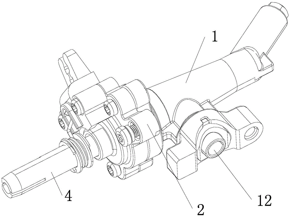
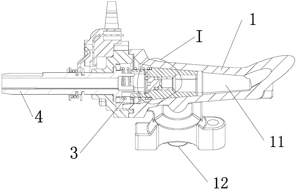
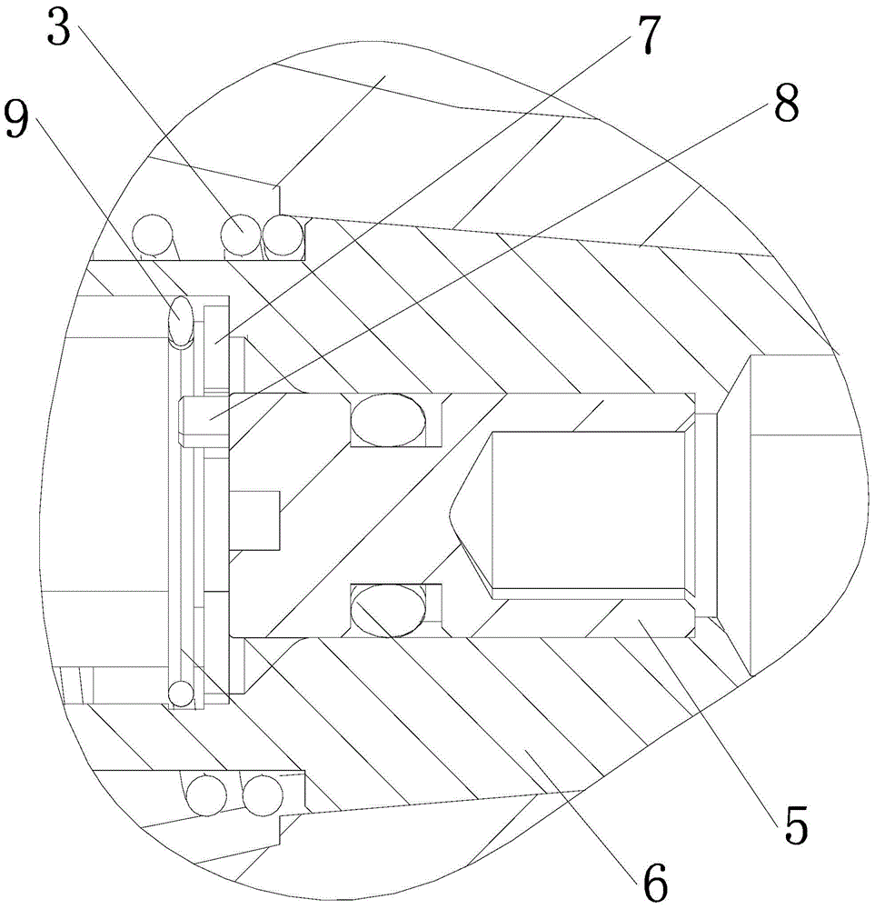
[0020] The present invention is a gas valve applicable to different gas sources, such as Figures 1 to 5 Shown, comprise valve body 1, valve seat 2, spool, spool spring 3 and rotating shaft 4, described spool includes inner and outer spool 5,6, and described inner spool 5 is near rotating shaft 4 The surface of that end is provided with an adjusting port 51 for inserting a screwdriver to rotate the inner valve core 5; no matter whether it is NG or LP gas source in the present invention, they all share the same large fire intake channel, and are similar to the gas valve whose patent number is 200810030076.3 It is basically the same, and the outer valve core 6 is also provided with a large fire inlet hole 61 for communicating with the outlet passage 11 and the inlet passage 12 of the valve body; the difference is that the structure is simpler and more reasonable. and the micro-flame adjustment structure, for this reason, the outer valve core 6 is provided with the first and seco...


PUM


Abstract

The invention discloses a gas valve suitable for different gas sources. An outer valve core is provided with first and second low fire air inlet holes which can be communicated with an air outlet passage and an air inlet passage of a valve body; an inner valve core is provided with a low fire flow through hole capable of communicating the second low fire air inlet hole with the air outlet passage and the air inlet passage when the inner valve core rotates; a limiting block which stops on the outer side of the inner valve core and cannot rotate in the hole is placed in the hole of the outer valve core, and is provided with a cambered limiting groove; the surface of the end, close to the rotating shaft, of the inner valve core is also provided with a limiting bump which falls into the cambered limiting groove; when the limiting bump swings from one end of the cambered limiting groove to the other end, the first low fire air inlet hole is communicated with the air outlet passage and the air inlet passage all the time, and the low fire flow through hole is switched between communication or plugging with the air outlet passage and the air inlet passage; an anti-drop structure for preventing the limiting block from dropping is arranged in the outer valve core. The gas valve has the advantages of more rational and simpler structure, lower production and material cost and high convenience in daily maintenance.

Description

technical field [0001] The invention relates to a gas valve, in particular to a gas valve applicable to different gas sources without replacing the valve core. Background technique [0002] We know that the gas sources used by gas valves mainly include liquefied petroleum gas (LP) and natural gas (NG). Due to the different characteristics of gas, the amount of intake air required under the same heat effect is different. Therefore, the early gas valves It can only be applied to one gas source, and it has been determined whether it is an LP gas valve or an NG gas valve during production. Later, people developed a spool-adjustable gas valve that can be used for LP and NG gas sources at the same time. By turning the spool, it can be used for LP or NG gas sources. For example, the Chinese patent number is 200810030076.3 gas valve. However, the patented spool adjustable structure is relatively complicated. It processes a threaded blind hole on the inner spool to screw the upper l...

Claims


Application Information

Patent Timeline
Patent Type & Authority Patents(China)
IPC IPC(8): F16K5/00F16K5/10F16K5/08
CPCF16K5/0207F16K5/103
Inventor 虞上海
Owner 广东金尚智能电气有限公司
Why Eureka
Eureka Blog
Learn More