CO2 high-temperature heat pump system

A high-temperature heat pump and gas-liquid separator technology, applied in the field of mechanical engineering, to achieve the effect of expanding the application range and improving cycle efficiency

Active Publication Date: 2015-06-03
NINGBO SAISEN ENERGY SAVING EQUIP CO LTD
View PDF4 Cites 9 Cited by
  • Summary
  • Abstract
  • Description
  • Claims
  • Application Information

AI Technical Summary

Problems solved by technology

[0005] The object of the present invention is to provide a CO 2 High-temperature heat pump system to solve the problems existing in the existing heat pump system when the water temperature is high, so that the high-temperature heat pump can be used in the field of industrial heating efficiently and stably

Method used


Image

  • CO2 high-temperature heat pump system

Examples


Embodiment Construction

[0017] The present invention will be described in further detail below in conjunction with the accompanying drawings.

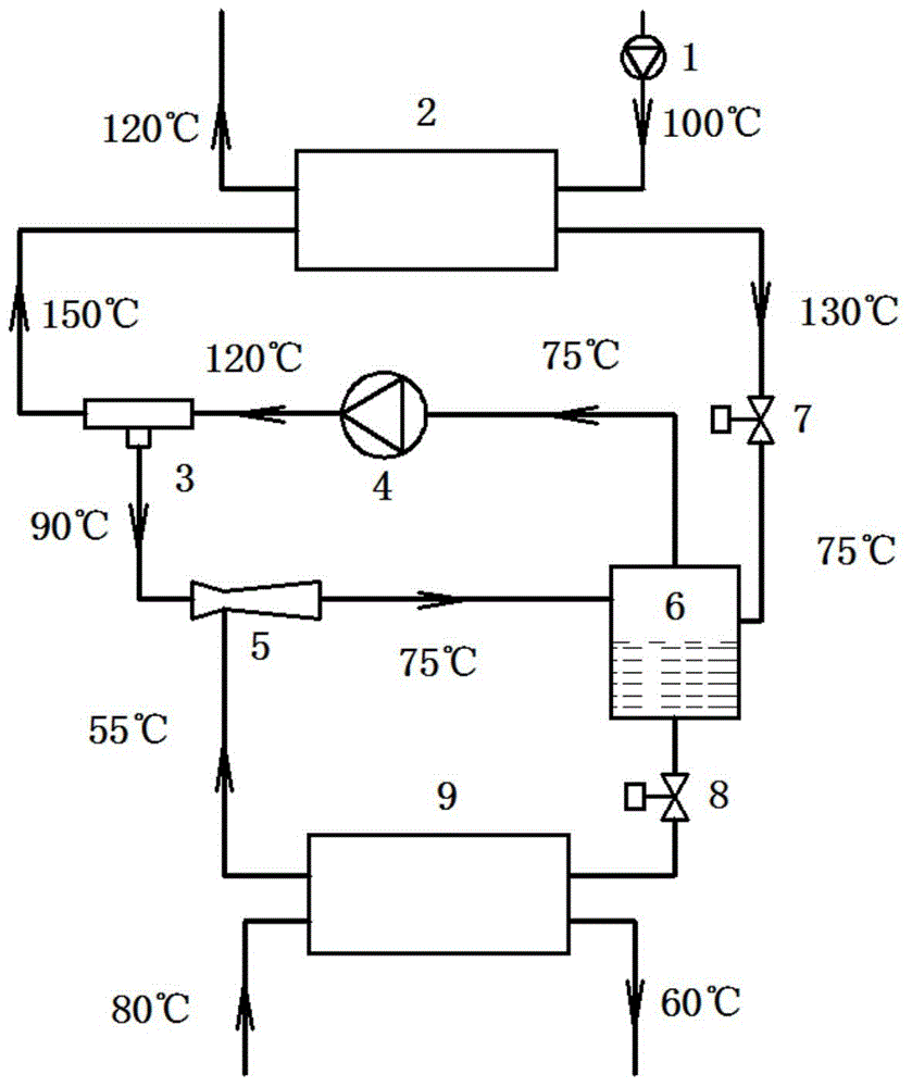
[0018] see figure 1 Shown, the present invention a CO 2 The high-temperature heat pump system includes a booster water pump 1 , a condenser 2 , a vortex tube 3 , a compressor 4 , an ejector 5 , a gas-liquid separator 6 , a first expansion valve 7 , a second expansion valve 8 and an evaporator 9 .

[0019] The outlet of the booster water pump 1 is connected to the water inlet of the condenser 2, and the water outlet of the condenser 2 is connected to the water outlet pipe.

[0020] The outlet of the compressor 4 is connected to the inlet of the vortex tube 3, the high temperature outlet of the vortex tube 3 is connected to the refrigerant inlet of the condenser 2, and the low temperature outlet of the vortex tube 3 is connected to the first inlet of the ejector 5; the refrigerant outlet of the condenser 2 Connect the gas-liquid separator 6 through the first ...


PUM


Abstract

The invention discloses a CO2 high-temperature heat pump system. The CO2 high-temperature heat pump system comprises a condenser, a vortex tube, a compressor, a gas-liquid separator, a first expansion valve, a second expansion valve and an evaporator, wherein an outlet of the compressor is connected with an inlet of the vortex tube; a high-temperature outlet of the vortex tube is connected with a refrigerating fluid inlet of the condenser; a low-temperature outlet of the vortex tube is connected with the gas-liquid separator; a refrigerating fluid outlet of the condenser is connected with the gas-liquid separator via the first expansion valve; a gas outlet of the gas-liquid separator is connected to an inlet of the compressor through a gas suction tube; a liquid outlet of the gas-liquid separator is connected to a first inlet of the evaporator via the second expansion valve; and a first outlet of the evaporator is connected with the gas-liquid separator. The vortex tube and an ejector are arranged on the heat pump system, a vortex shedding effect of the vortex tube is utilized, water with high temperature can be provided by the condenser under the condition that a heat pump has constant exhaust pressure, and the application range of the high-temperature heat pump is expanded further; and moreover, the air suction pressure of the compressor can be increased with the aid of the ejector, and the energy efficiency of the heat pump is improved.

Description

【Technical field】 [0001] The invention belongs to the technical field of mechanical engineering and relates to a CO 2 High temperature heat pump system. 【Background technique】 [0002] Mechanical compression heat pump technology uses a small amount of high-grade mechanical energy to complete the cycle of refrigerant in the system by using a compressor, extract heat from a lower temperature heat source and heat other media, that is, by consuming a small amount of high-grade energy, the low Grade energy is upgraded to high grade energy. The advantage of high-temperature heat pump technology is that it can use a heat source at a lower temperature of 40°C-50°C to generate hot water as high as 80°C-120°C, and provide the energy originally discharged as waste heat to occasions that consume a large amount of heat energy. The utilization rate of energy is increased, and it has great advantages in energy saving and environmental protection. [0003] At present, heat pumps are comm...

Claims


Application Information

Patent Timeline
Patent Type & Authority Applications(China)
IPC IPC(8): F25B9/04F25B30/06
CPCF25B9/04F25B30/06F25B2309/06
Inventor 曹锋何永宁金磊邢子文
Owner NINGBO SAISEN ENERGY SAVING EQUIP CO LTD
Why Eureka
Try Eureka