
Microwave induction control method and microwave induction control device

A microwave induction and control device technology, applied in the direction of measuring devices, program control, computer control, etc., can solve the problems of children's electric shock danger, misoperation, noise affecting others, etc. Effect of Power Consumption Reduction

Active Publication Date: 2015-06-03
感仁科技(深圳)有限公司
View PDF5 Cites 23 Cited by
  • Summary
  • Abstract
  • Description
  • Claims
  • Application Information

AI Technical Summary

Problems solved by technology

[0002] With the continuous progress of the social economy and the gradual improvement of people's living standards, electrical products have penetrated into all aspects of our lives. At the same time, electrical automation control technology has affected all aspects of people's lives. Wide range, but because the sound sensor needs a louder sound to be sensed by it, it is easy to generate noise to affect others, and it is also prone to misoperation due to the influence of the natural environment. In places where electricity is used, various mechanical switching appliances are still widely used. People must manually turn on the switch to provide power or turn off the switch to cut off the power to realize the control of electrical functions.
At present, the mechanical control switch method used is prone to leakage, aging and failure in humid or dusty environments, especially when children are prone to electric shock hazards when manually operating the power switch

Method used


Image

  • Microwave induction control method and microwave induction control device
  • Microwave induction control method and microwave induction control device
  • Microwave induction control method and microwave induction control device

Examples


no. 1 example

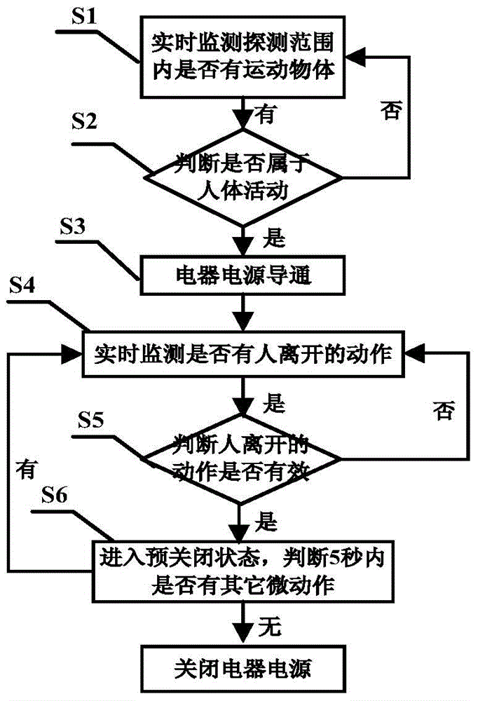
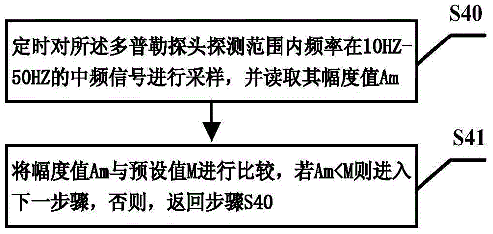
[0045] image 3 yes figure 2 The specific work flow chart of shown step S4, Figure 4 yes figure 2 The specific work flow chart of step S4 shown. In the method provided in the second embodiment of the present invention, see image 3 , Figure 4 As shown, relative to the first embodiment of the present invention, the method in this embodiment may further include the following steps:

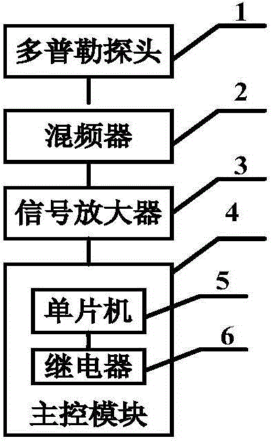
[0046] S40, the microwave induction control device enters the standby state, the single-chip microcomputer 5 controls the Doppler radar probe 1 to transmit pulsed microwave signals to the predetermined detection range, and the Doppler radar probe 1 converts the reflected frequency by the mixer 2 at a predetermined frequency The intermediate frequency signal is sampled, and the amplitude value Am of the collected intermediate frequency signal is read (here m is a natural number of 1, 2, 3..., Am refers to the maximum value of the amplitude value of the intermediate frequency signal sampled i...


PUM


Abstract

The invention discloses a microwave induction control method and a microwave induction control device and relates to the technical field of application of microwave sensors. According to the method, an action system for judging whether persons enter or leave the scene or not is established by using the Doppler effect through the microwave induction control device; a switch of a power supply of an electrical appliance is controlled by identifying the action that human bodies enter or leave the scene; the microwave induction control device adopted by the method can be arranged inside the electrical appliance, so that the electrical appliance adopts a closed structure, and moisture resistance and electric shock prevention can be realized. In addition, according to the method, the action whether the human bodies leave or not can be identified, and the power supply of the electrical appliance is automatically closed when the human bodies leave the detection range and no person exist in the detection range. Besides, the device is low in power consumption; when the device is installed on the electrical appliance for use, the standby power consumption of the electrical appliance can be greatly reduced, and further the aims of saving energy and electricity are achieved.

Description

technical field [0001] The invention relates to the technical field of microwave sensor applications, and more specifically, to a microwave induction control method and device. Background technique [0002] With the continuous progress of the social economy and the gradual improvement of people's living standards, electrical products have penetrated into all aspects of our lives. At the same time, electrical automation control technology has affected all aspects of people's lives. Wide range, but because the sound sensor needs a louder sound to be sensed by it, it is easy to generate noise to affect others, and it is also prone to misoperation due to the influence of the natural environment. In places where electricity is used, various mechanical switching appliances are still used in large quantities. People must manually turn on the switch to provide power or turn off the switch to cut off the power to realize the control of electrical functions. At present, the mechanica...

Claims


Application Information

Patent Timeline
Patent Type & Authority Applications(China)
IPC IPC(8): G05B19/042G01S13/04
CPCG05B19/042G05B2219/25338
Inventor 刘仪曾庆刚刘宁
Owner 感仁科技(深圳)有限公司
Learn More