
PMFCL (permanent-magnet-biased fault current limiter) magnetic current thermal coupling modeling method

A technology of fault current limiter and modeling method, applied in instruments, special data processing applications, electrical digital data processing, etc., can solve the problems of distortion, complex magnetic leakage components, etc., and achieve the effect of reducing occupancy

Active Publication Date: 2015-06-03
STATE GRID CORP OF CHINA +1
View PDF2 Cites 6 Cited by
  • Summary
  • Abstract
  • Description
  • Claims
  • Application Information

AI Technical Summary

Problems solved by technology

This hybrid magnetic circuit structure leads to more complex magnetic leakage components, mainly including the leakage magnetic field between the permanent magnet and the surface of the iron core, the leakage magnetic field between turns of the winding, and the leakage magnetic field at the corner or joint of the iron core. When the system is short-circuited, the leakage magnetic field Distortion will occur. In order to analyze the magnetic efficiency of the current limiter more effectively, it is necessary to establish a reliable magnetic flux leakage analysis model based on experimental research.

Method used

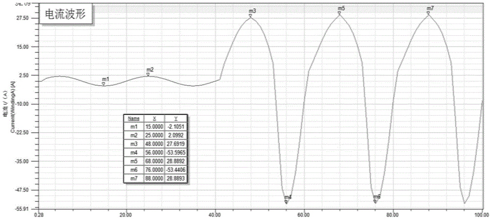
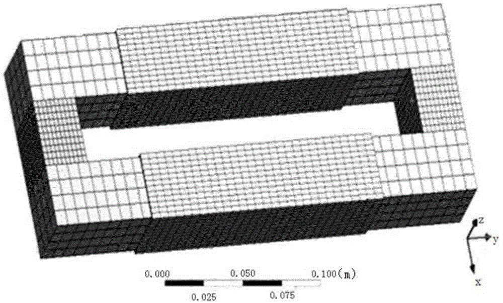

Image

  • PMFCL (permanent-magnet-biased fault current limiter) magnetic current thermal coupling modeling method
  • PMFCL (permanent-magnet-biased fault current limiter) magnetic current thermal coupling modeling method
  • PMFCL (permanent-magnet-biased fault current limiter) magnetic current thermal coupling modeling method

Examples


Embodiment Construction

[0043] Below in conjunction with accompanying drawing and embodiment the present invention will be further described:

[0044] Working principle of permanent magnet saturation fault current limiter

[0045] Current Limiting Mechanism Analysis of Permanent Magnet Saturation Fault Current Limiter (hereinafter referred to as PMFCL) Based on Magnetic Field

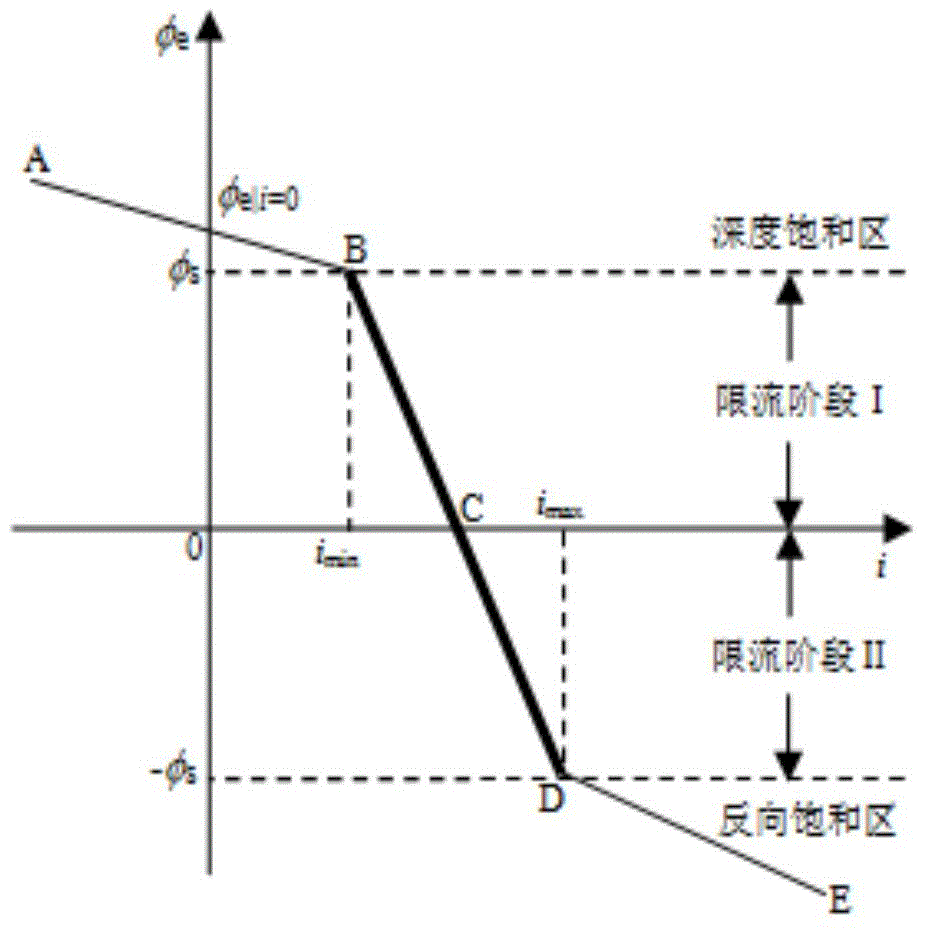
[0046] figure 1 The core magnetic flux φ in the half-wave current-limiting topology of the linear PMFCL is given e The relationship curve with winding current i. Among them, the broken line ABCDE is the trajectory of the operating point of the half-wave current-limiting topology core, and AB, BD and DE represent the forward saturation region, desaturation region and reverse saturation region of the current limiter, respectively. When the system is working normally, the strong bias magnetic field generated by the permanent magnet keeps the iron core in the deep saturation region AB, and the magnetic flux of the iron core sat...


PUM


Abstract

The invention discloses a PMFCL (permanent-magnet-biased fault current limiter) magnetic current thermal coupling modeling method. The PMFCL magnetic current thermal coupling modeling method includes establishing a 2D model of a half-wave current-limiting topological structure of the PMFCL; employing finite element software Ansoft to simulate the model; establishing a 3D model of the half-wave current-limiting topological structure of the PMFCL by the aid of the Ansoft; establishing a transient thermal analysis model in the ANSYS, subjecting the transient thermal analysis model to finite element mesh generation and subjecting a temperature field to graph mapping to the 3D model of the half-wave current-limiting topological structure of the PMFCL, and accordingly obtaining a temperature field calculation result of a PMFCL device at any moments. According to the arrangement, electromagnetic fields and current vectors of a winding and components of a linear PMFCL are analyzed and calculated with thermal fields to obtain magnetic-current-thermal coupling analysis, accordingly imparting a significant reference for material types and parameter designs of the PMFCL.

Description

technical field [0001] The invention belongs to the field of power system fault current limiting, in particular to a magnetic current thermal coupling modeling method for a permanent magnet saturation fault current limiter. Background technique [0002] With the increasing scale of my country's power grid, the rapid growth of power system load, the continuous operation of large-capacity units, and the interconnection of power grids in various regions, the level of short-circuit in the power system is increasing day by day. The current level has approached or even exceeded the maximum allowable level stipulated by the electric power regulations. Excessive short-circuit current will not only cause the voltage and frequency instability of the power system, but also produce strong thermal effects and electrodynamic shocks, which will damage electrical equipment and its insulation. Furthermore, problems such as step voltage and electromagnetic interference to communication equipm...

Claims


Application Information

Patent Timeline
Patent Type & Authority Applications(China)
IPC IPC(8): G06F17/50
Inventor 段玉兵胡晓黎雍军杨波孙晓斌张皓
Owner STATE GRID CORP OF CHINA
Learn More