Dual-stopband UWB (Ultra-wide Bandwidth) antenna with steep stopbands

A dual-stop-band, steep technology, applied in the direction of antenna, antenna coupling, radiating element structure, etc., can solve the problems of difficult adjustment of the center frequency of the stop-band, unfavorable system integration, large antenna volume, etc., and achieves compact structure, low cost, Easy to process effect

Inactive Publication Date: 2015-06-03
HARBIN HESON SCI & TECH
View PDF0 Cites 9 Cited by
  • Summary
  • Abstract
  • Description
  • Claims
  • Application Information

AI Technical Summary

Problems solved by technology

However, these methods have limitations, such as the large size of the antenna, which is not

Method used


Image

  • Dual-stopband UWB (Ultra-wide Bandwidth) antenna with steep stopbands
  • Dual-stopband UWB (Ultra-wide Bandwidth) antenna with steep stopbands
  • Dual-stopband UWB (Ultra-wide Bandwidth) antenna with steep stopbands

Examples


Embodiment Construction

[0027] The present invention designs a UWB antenna with double stop bands and steep stop bands, which suppresses the interference of the UWB system to the RFID system (6.8 GHz) and the WLAN system (5.15-5.35 GHz).

[0028] Below in conjunction with accompanying drawing, invention is described in more detail:

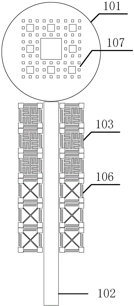
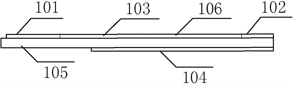
[0029] Such as figure 1 As shown, a dual stopband UWB antenna with a steep stopband of the present invention, a radiation unit (101) on a dielectric substrate, a square etched fractal structure (107), an impedance matching input microstrip line (102), and a broken line EBG The electromagnetic bandgap structure (103) and the cross-type EBG electromagnetic bandgap structure (106) are made of copper.

[0030] Such as figure 1 As shown, the square etched fractal structure (107) on the radiating unit can improve the stopband attenuation suppression.

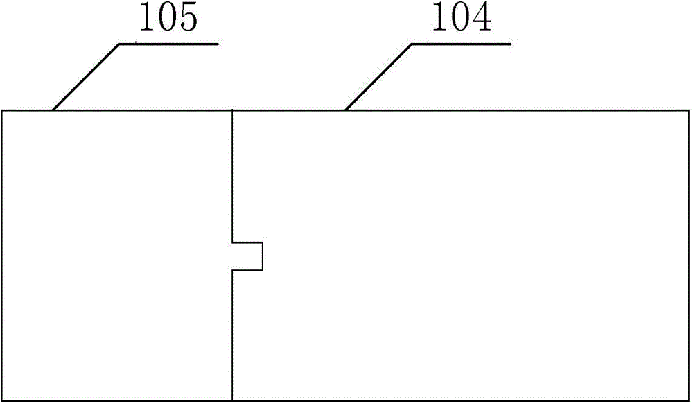
[0031] An example of the present invention is figure 2 As shown, the dielectric substrate (105) is a GML1000 material wit...


PUM


Abstract

The invention relates to a dual-stopband UWB (Ultra-wide Bandwidth) antenna with steep stopbands, relating to a UWB antenna. The dual-stopband UWB antenna with the steep stopbands, is formed by a dielectric substrate (105), a radiating element (101) above the dielectric substrate, a square etching fractal structure (107), an impedance matching input microstrip line (102), a fold line type EBG (Electromagnetic Band Gap) structure (103), a criss cross EBG structure (106) and a metal earth plate (104) under the dielectric substrate. According to the dual-stopband UWB antenna with the steep stopbands, the radiating element, the impedance matching input microstrip line and the metal earth plate are utilized to realize passband width required by UWB, and the dual-stopband characteristic of the steep stopbands is realized by utilizing the two groups of EBG structures and the square etching fractal structure above the radiating element. According to the antenna provided by the invention, the two stopbands are respectively close to 5.2Ghz and 6.8GHz, so that the interference of a UWB system on an RFID (Radio Frequency Identification Device) system (6.8GHz) and a WLAN (Wireless Local Area Network) system (5.15-5.35GHz) is restrained.

Description

technical field [0001] The invention relates to an ultra-wideband band-stop antenna, in particular to a dual-stop-band UWB antenna with steep stop bands, which can suppress the mutual interference between the ultra-wide band system and the RFID and WLAN systems. Background technique [0002] In February 2002, the US Federal Communications Commission (FCC) approved the 3.1-10.6GHz frequency band for commercial communications, so UWB is widely used. [0003] However, due to the wide frequency band covered by UWB communication, some frequency bands share frequency band resources with other wireless systems, and may interfere with other systems, such as Wimax system (3.2-3.5GHz), WLAN system (5.15-5.35GHz), ( 5.725-5.825GHz) and RFID systems (6.8GHz). How to solve co-channel interference has become an important content of UWB research, so ultra-wideband antennas with stopband characteristics have high practical value. [0004] In recent years, there have been many design ideas...

Claims


Application Information

Patent Timeline
IPC IPC(8): H01Q1/38H01Q1/52H01Q13/08
Inventor 喻人杰李琦苏畅
Owner HARBIN HESON SCI & TECH
Why Eureka
Try Eureka