

Ground reflector in cable network structure
A cable-net structure and reflector technology, applied in the fields of communication and electronics, can solve the problems of increasing gravity deformation, and the cable-net structure cannot be directly used on the ground, etc., and achieves the effects of reducing the impact, shortening the development cycle, and simplifying the structure.
- Summary
- Abstract
- Description
- Claims
- Application Information
AI Technical Summary
Problems solved by technology
Method used
Image

Examples
Embodiment 1
[0048] Embodiment 1, a reflector with a ring frame column type cable net reflective surface structure.
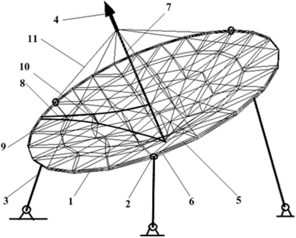
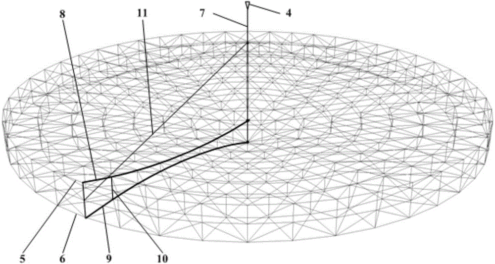
[0049] refer to figure 1 with figure 2 , the reflector of this example includes: a plurality of rectangular truss units 1, a plurality of ring structure connection joints 2, azimuth and pitch control devices 3, a feed source 4, an upper ring 5, a lower ring 6, a central cylinder 7 and Longitudinal support cables 10. Every two rectangular truss units 1 are fixedly connected by a ring structure connection joint 2 to form a circular truss structure composed of an upper ring 5 and a lower ring 6; the central cylinder 7 is arranged in the center of the circular truss structure, and the feed source 4 Installed above the central cylinder 7; between the central cylinder 7 and the upper end ring 5 of the circular truss structure, a first layer of criss-cross flexible cable net is installed to form a reflective surface of the mesh cable 8, and the mesh surface cable A wire mesh i...
Embodiment 2
[0055] Embodiment 2, a reflector with a ring-rib-column cable-net reflective surface structure.
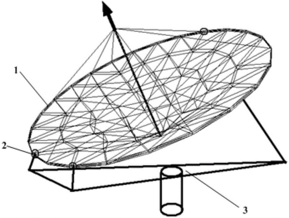
[0056] refer to image 3 with Figure 4 , the reflector of this example includes: a plurality of rectangular truss units 1, a plurality of ring structure connection joints 2, azimuth and pitch control devices 3, a feed source 4, an upper ring 5, a lower ring 6, a central cylinder 7, A plurality of rib bar units 12 and a plurality of rib structure connection joints 13, every two rectangular truss units 1 are fixedly connected by a ring structure connection joint 2, forming a circular truss structure composed of an upper ring 5 and a lower ring 6; The central cylinder 7 is set at the center of the circular truss structure, and the feed source 4 is installed above the central cylinder 7; the first layer of criss-cross flexible Cable net, the mesh cable 8 forming the reflective surface, the mesh cable is bound with a wire mesh; the second layer of crisscross flexible cable net is in...
PUM
| Property | Measurement | Unit |
|---|---|---|
| Caliber | aaaaa | aaaaa |
| Outer diameter | aaaaa | aaaaa |
| The inside diameter of | aaaaa | aaaaa |
Abstract
Description
Claims
Application Information