High-temperature resistance rectangular electrical connector

An electric connector and high temperature resistant technology, which is applied in the direction of connection and connection device components, circuits, etc., can solve the problems of reducing signal transmission efficiency, rubber pad aging, carbonization, etc., and achieve high work safety and reliability, high temperature resistance performance Good, reasonable selection of materials

Inactive Publication Date: 2015-06-03
SUZHOU HUAZHAN SPACE APPLIANCE
View PDF5 Cites 5 Cited by
  • Summary
  • Abstract
  • Description
  • Claims
  • Application Information

AI Technical Summary

Problems solved by technology

With the development of oil drilling technology, the drilling depth continues to extend, and the temperature resistance requirements of drilling equipment and instruments are getting higher and higher. The connectors of the prior art have the following problems in the application process: ①. After long-term high-temperature operation of the contact parts , Copper diffuses to the surface of the gold layer and is oxidized at high temperature, so that the surface of the contact is blackened, which directly affects the reliability of signal transmission; ②, the material of the outer casing is carbonized, resulting in a decrease in the insulation resistance between the contacts at high temperature; ③, After working at high temperature for a long time, the potting compound is separated from the shell assembly, and the potting compound itself cracks; ④, the rubber pad ages, loses its elasticity, and cracks after being stressed, which makes the sealing function of the connector interface invalid; ⑤, the wire is oxidized, causing the The resistance of the wire increases, causing the wire to heat up and reducing the transmission efficiency of the signal

Method used


Image

  • High-temperature resistance rectangular electrical connector
  • High-temperature resistance rectangular electrical connector
  • High-temperature resistance rectangular electrical connector

Examples


Embodiment Construction

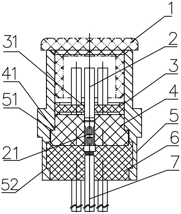
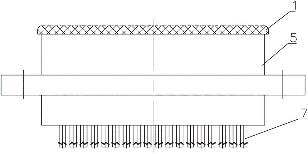
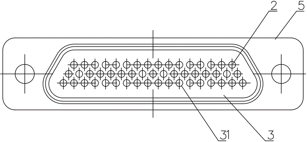
[0013] refer to Figure 1 to Figure 5 , the present invention includes an electrostatic dustproof cover 1, a contact piece 2, a rubber pad 3, a base 4, a casing 5, a potting glue 6 and a wire 7, the contact piece 2 is a rod member provided with a crimping cylinder 21, and the casing 5 is a rectangular shell provided with a base step 51 and a potting rubber ring groove 52, the rubber pad 3 is a plate-shaped body provided with a contact hole 31, and the outer side of the base 4 is provided with a notch 41; the contact The crimping barrel 21 of 2 is crimped with one end of the wire 7 to form a contact assembly 8, and then the contact assembly 8 is assembled to the corresponding position of the injection mold of the base, and the base 4 is formed into a base assembly 9 after injection molding. The base assembly 9 is loaded into the shell 5 from the tail end of the shell 5, and the notch 41 of the base 4 touches the base step 51 in the shell 5, and the potting glue 6 is poured into...


PUM


Abstract

The invention discloses a high-temperature resistance rectangular electrical connector which comprises an electrostatic dustproof cover, a contact element, a rubber pad, a base, a housing, a pouring sealant and a wire. The housing is a rectangular shell with a pouring sealant ring groove; a pressure welding barrel of the contact element is pressure-welded with one end of the wire to form a contact element assembly; the contact element assembly is arranged in a base injection mould; after the base is subjected to injection molding, a base assembly is formed; the base assembly is arranged inside from the tail end of the housing; the pouring sealant is poured into a cavity formed by the pouring sealant ring groove of the housing and the base assembly; the rubber pad is arranged inside from the top end of the housing; the electrostatic dustproof cover is arranged at the top end of the housing. Aiming at the practical functions of key parts of the electrical connector, the high-temperature resistance rectangular electrical connector selects different materials, adopts different processes and has the advantages of being reasonable in material selection, simple in structure, good in high-temperature resistance, safe in working and high in reliability by reasonable structural optimal combination.

Description

technical field [0001] The invention relates to the technical field of electrical connectors, in particular to a high temperature resistant rectangular electrical connector. Background technique [0002] The ordinary rectangular electrical connectors in the prior art generally have a temperature resistance range of -55°C to +125°C, while the high temperature resistant rectangular electrical connectors can only be used in the temperature range of -55°C to +200°C. working environment. Its structure and process are as follows: the base and the shell are bonded to form a shell assembly, and the contact assembly is formed after the contact is crimped to the wire, and then the contact assembly is put into the base hole and assembled with the shell assembly. together, and inject potting compound into the potting cavity at the end of the shell assembly, so as to fix the contact assembly in the shell assembly. With the development of oil drilling technology, the drilling depth is c...

Claims


Application Information

Patent Timeline
Patent Type & Authority Applications(China)
IPC IPC(8): H01R13/405H01R13/03H01R13/52
CPCH01R13/533H01R13/03H01R13/502H01R13/5213
Inventor 陈银桂李振丁涛
Owner SUZHOU HUAZHAN SPACE APPLIANCE
Why Eureka
Try Eureka