
Wireless power transmission system with double coils wound in parallel, and output power distribution method of system
A technology of wireless power transmission and output power, which is applied in the direction of electromagnetic wave systems, electrical components, circuit devices, etc., can solve the problems that the output current cannot meet the needs of high-power power transmission, the promotion limit of a single inverter, and affect the stability of the system. The power adjustment method is simple, the effect of reducing capacity and increasing redundancy
Patent Information
- Authority / Receiving Office
- CN · China
- Current Assignee / Owner
- Publication Date
- 2015-06-03
Smart Images
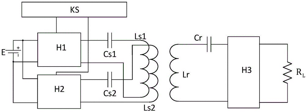
Figure 1 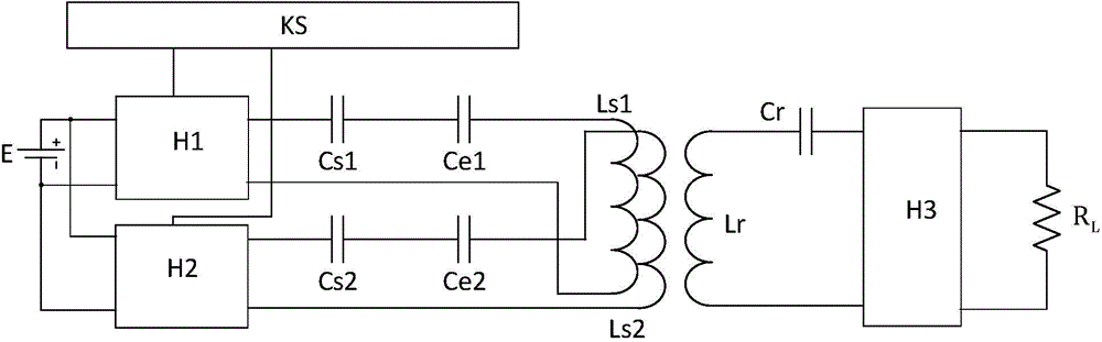
Figure 2 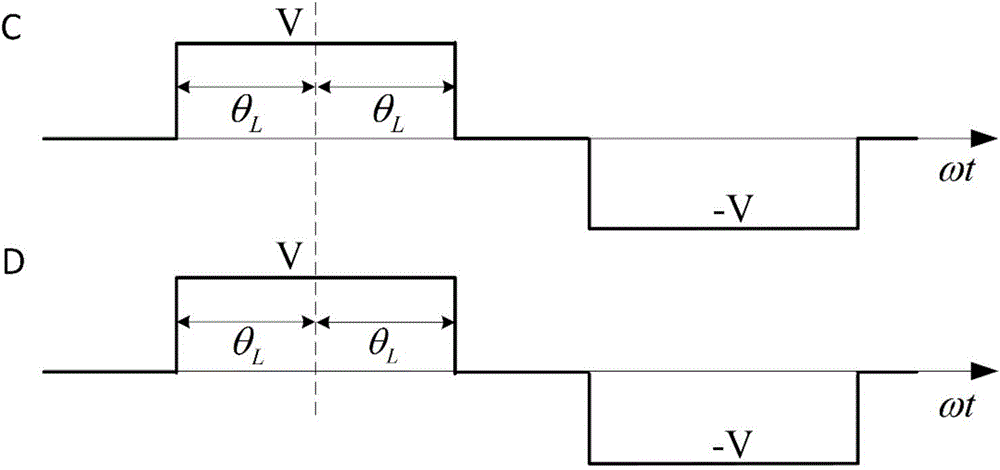
Figure 3
Abstract
Description
technical field
[0001] The invention relates to the technical field of wireless power transmission, in particular to a wireless power transmission system with double coils wound in parallel and an output power distribution method thereof. Background technique
[0002] The application of wireless power transmission technology to the power supply system of rail transit can avoid the potential safety hazards caused by the contact and sliding power supply of exposed conductors such as the existing catenary or the third rail, and there are no disadvantages such as carbon deposition and friction loss, and it has low maintenance costs. It has the advantages of safety, reliability and high practicability.
[0003] The main composition and working process of the existing wireless power transmission system are: the power frequency alternating current is rectified into direct current, and the direct current is inverted into high frequency alternating current after passing through the i...
Examples
Embodiment
[0044] figure 1 , figure 2 and Figure 4 It shows that a specific embodiment of the present invention is a wireless power transmission system with double coils wound in parallel, including a sending end and a receiving end, wherein:
[0045] A wireless power transmission system with double coils wound side by side, including a sending end and a receiving end, its structure is:
[0046] The specific composition of the sending end is: the two ends of the DC power supply E are connected in parallel with the inverter one H1 and the inverter two H2; the inverter one H1 is connected with the sending coil one Ls1 through the compensation capacitor Cs1 and the power distribution capacitor Ce1 in turn, Inverter 2 H2 is sequentially connected to sending coil 2 Ls2 through compensation capacitor 2 Cs2 and power distribution capacitor 2 Ce2; sending coil 1 Ls1 and sending coil 2 Ls2 are identical and wound on the same magnetic core;
[0047] The receiving end is sequentially connected...