

Main die rotary type high-speed cold heading machine
A technology of rotary and cold heading machines, which is applied in the directions of heading presses, swaging presses, forging/pressing/hammering machines, etc., which can solve problems such as poor working stability, low working efficiency, and short die life, and achieve Convenient debugging, high work efficiency and high processing precision
- Summary
- Abstract
- Description
- Claims
- Application Information
AI Technical Summary
Problems solved by technology
Method used
Image

Examples
Embodiment Construction
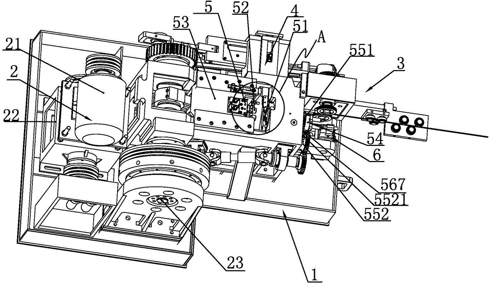
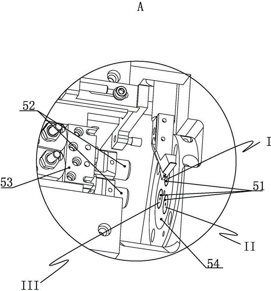
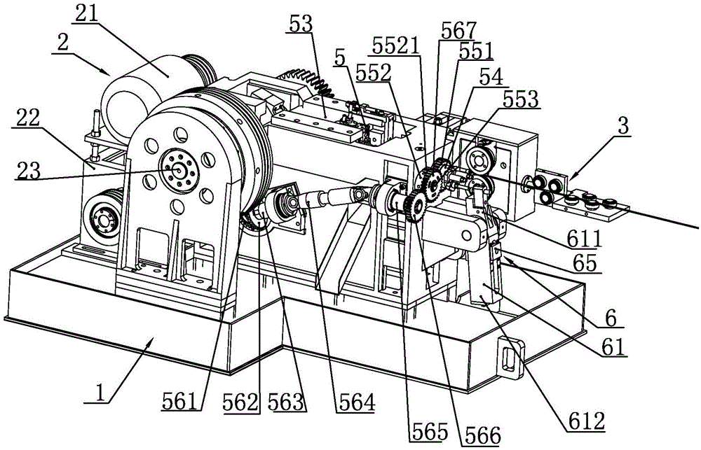
[0032] Such as picture 1~picture As shown in 8, a main mold rotary high-speed cold heading machine disclosed by the present invention includes a fuselage 1, a power device 2 installed on the fuselage 1, a wire feeding device 3, a cutting and feeding device 4, a piercing Device 5 and material return device 6; Wherein power unit 2 comprises drive motor 21, gearbox 22, crankshaft 23 and countershaft 24, and drive motor 21 output end is connected with gearbox 22, and the output end of gearbox 22 is through pulley, Transmission belt( picture (not shown) is driven to connect the crankshaft 23, and the crankshaft 23 is connected to the countershaft 24 through the gear pair transmission; the piercing device 5 includes a main die 51, at least two dies 52 and a die slide 53, and the die 52 is installed on the die slide On the seat 53, the die slide seat 53 is slidably fitted on the fuselage 1. Described upsetting device 5 also includes main mold rotary mechanism, and main mold rotary...
PUM
 Abstract
Description
Claims
Application Information