
Lamination control system, method and device

A technology of control system and limit device, applied in the direction of lamination device, control lamination, chemical instruments and methods, etc., can solve problems such as low production efficiency, and achieve the effect of improving productivity, increasing speed and ensuring lamination accuracy

Active Publication Date: 2017-02-01
XIAOMI INC
View PDF6 Cites 0 Cited by
  • Summary
  • Abstract
  • Description
  • Claims
  • Application Information

AI Technical Summary

Problems solved by technology

[0003] When laminating TP and LCD in a vacuum chamber, since there is no fixing device to fix TP, there will be misalignment in X and Y directions between TP and LCD in a vacuum state; in addition, in order to completely remove TP It also takes a certain amount of time to vacuumize the metal cavity, resulting in low production efficiency

Method used


Image

  • Lamination control system, method and device
  • Lamination control system, method and device
  • Lamination control system, method and device

Examples


Embodiment Construction

[0048] Reference will now be made in detail to the exemplary embodiments, examples of which are illustrated in the accompanying drawings. When the following description refers to the accompanying drawings, the same numerals in different drawings refer to the same or similar elements unless otherwise indicated. The implementations described in the following exemplary examples do not represent all implementations consistent with the present invention. Rather, they are merely examples of apparatuses and methods consistent with aspects of the invention as recited in the appended claims.

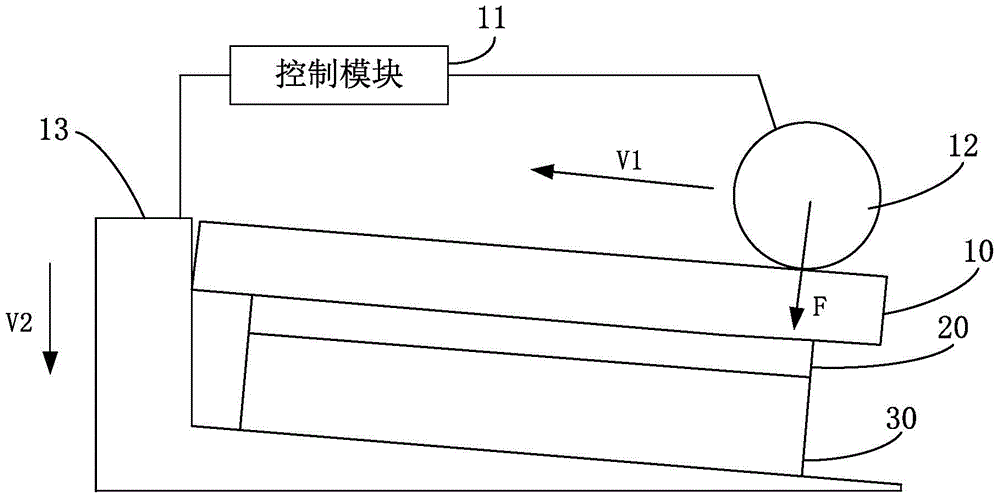
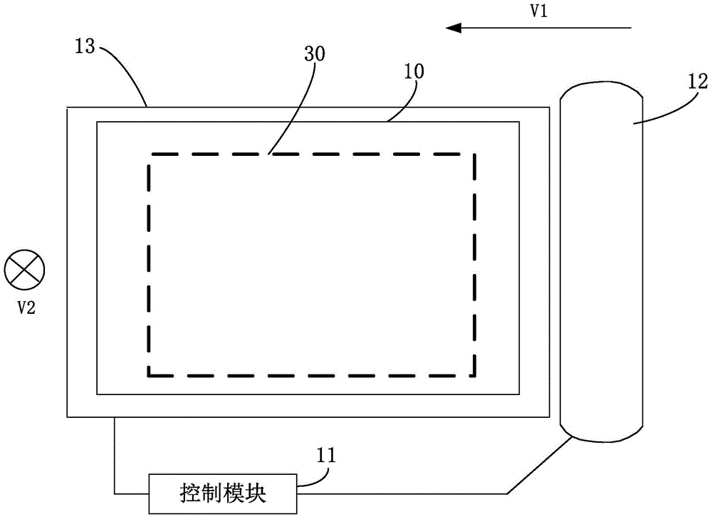
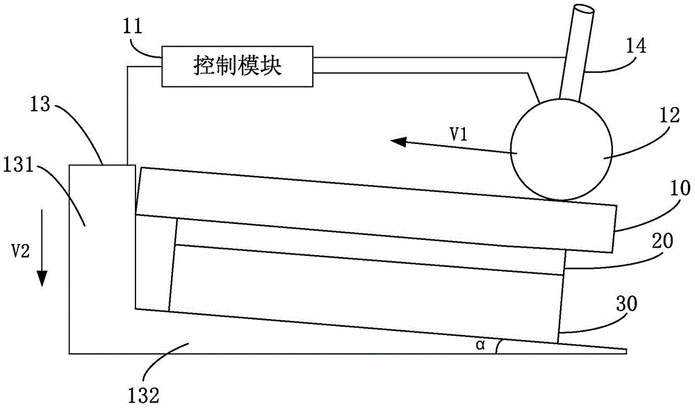
[0049] Figure 1A is one of the structural diagrams of a bonding control system shown according to an exemplary embodiment, Figure 1B It is the second structural diagram of the lamination control system shown according to an exemplary embodiment; as Figure 1A and Figure 1B As shown, after the alignment of TP10 and LCD30 is completed, TP10 can be moved to LCD30 by the laminating robot, TP10 i...


PUM


Abstract

The present disclosure relates to a lamination control system, method and device, which are used to effectively eliminate air bubbles between TP and LCD and prevent misalignment of TP and LCD during lamination. The bonding control system includes: a control module, a bonding roller, and a limiting device; the control module is configured to determine the first moving speed of the bonding roller and the second moving speed of the limiting device; The bonding roller is configured to roll from one side of the TP to the other side of the TP along a first direction according to the first moving speed; the limiting device is configured to limit the The TP moves relative to the LCD and moves along a second direction according to the second moving speed. The disclosed technical solution can discharge the air between the TP and the LCD, increase the speed of full bonding of the TP and the LCD, ensure that the bonding between the TP and the LCD will not cause dislocation between the TP and the LCD, and ensure the bonding accuracy.

Description

technical field [0001] The present disclosure relates to the technical field of electronic product production technology, in particular to a bonding control system, method and device. Background technique [0002] As smart phones have continuously improved display optical performance requirements, the full lamination process of touch screen (Touch Panel, TP for short) and liquid crystal display (Liquid Crystal Display, LCD for short) is more and more widely used. Related technology After aligning the TP's View Area (referred to as VA) and the LCD's effective display area (referred to as AA), fix the LCD machine while holding it, and the manipulator will paste it The TP of Optical Clear Adhesive (OCA) is moved to the top of the LCD, and the TP and LCD are bonded together in a vacuumed metal cavity. [0003] When laminating TP and LCD in a vacuum chamber, since there is no fixing device to fix TP, there will be misalignment in X and Y directions between TP and LCD in a vacuum...

Claims


Application Information

Patent Timeline
Patent Type & Authority Patents(China)
IPC IPC(8): B32B41/00B32B38/00B32B37/00
CPCB32B37/00B32B38/00B32B41/00B32B37/003B32B37/0046B32B37/12B32B38/1841B32B2309/14B32B2309/72B32B2457/202B32B2457/208B32B37/10B32B2309/68G02F1/1303G06F2203/04103G02F1/13G06F3/041G02F1/13338G02F2202/28
Inventor 唐恒钧石莎莎胡绍星
Owner XIAOMI INC
Learn More