Floating type wave energy extraction device based on original overwater structures

A technology for extracting device and wave energy, applied in ocean energy power generation, engine components, machines/engines, etc., can solve problems such as high cost and complex structure, and achieve the effect of reducing construction costs, optimizing operating conditions, and reducing costs

Inactive Publication Date: 2015-06-10
DALIAN UNIV OF TECH
View PDF5 Cites 6 Cited by
  • Summary
  • Abstract
  • Description
  • Claims
  • Application Information

AI Technical Summary

Problems solved by technology

According to its operating principle, the length of the wave surface raft device generally reaches the scale of the wavelength, often exceeding 100 meters, and the hydraulic compartment is in the water, and the movable parts such as the hydraulic piston rod penetrate the bulkhead. The structure is complex and requires strict sealing and sealing. Anti-seawater corrosion measures, the above reasons make its cost very expensive
Floating devices such as Powerbuoy are also offshore floating devices. Their size is much smaller than that of wave surface rafts, and their deployment is more flexible. However, the wave energy extracted by a single machine is less, and the hydraulic pressure and generators are also located in sealed cabins on the water. , which is similar to the problem faced by the wave surface raft device, and is also expensive

Method used


Image

  • Floating type wave energy extraction device based on original overwater structures
  • Floating type wave energy extraction device based on original overwater structures
  • Floating type wave energy extraction device based on original overwater structures

Examples


Embodiment Construction

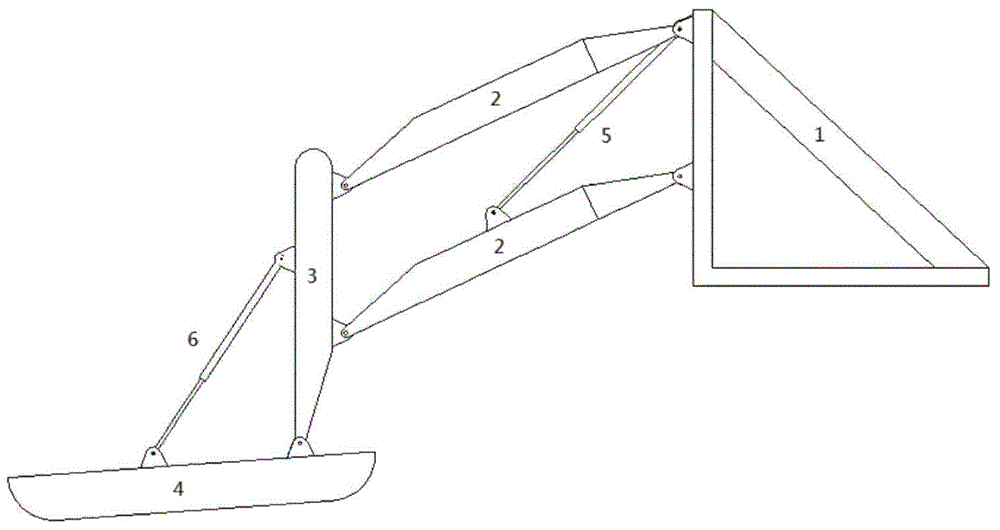
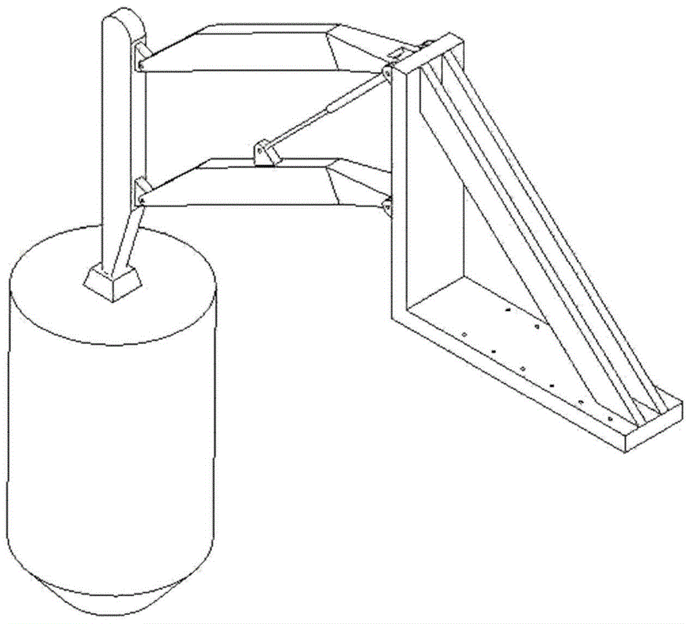
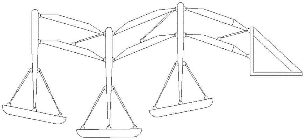
[0020] In the following, with reference to the accompanying drawings, the device of a modular unit including a support and a raft floating body is taken as an example to describe the device in detail, see figure 1 shown. The support 1 is fixedly installed on the inherent water structure, and the upper and lower crossbars 2 of the parallelogram structure are respectively hinged on the fixed support 1, and the longitudinal bar 3 forms a parallelogram with the support 1 and the crossbar 2. Because the support 1 is a vertical structure, according to the principle of parallelogram with opposite sides parallel, the longitudinal rod 3 can only move up and down, which ensures the up and down displacement of the floating body. The floating body 4 is installed at the lower end of the vertical rod 3, the hydraulic cylinder a5 is connected between the cross rod and the support, and the hydraulic cylinder b6 is connected between the floating body and the vertical rod.

[0021] When the fl...


PUM


Abstract

The invention provides a floating type wave energy extraction device based on original overwater structures, and belongs to the technical field of utilization of marine renewable energy. The floating type wave energy extraction device structurally comprises a support, cross bars, a longitudinal bar, a floating body and hydraulic cylinders, wherein the support, the longitudinal bar and two cross bars form a parallelogram linkage mechanism; the floating body is mounted at the lower end of the longitudinal bar and drives the parallelogram linkage mechanism to move longitudinally so as to provide energy for a hydraulic cylinder I between the support and the cross bars; the floating body and the longitudinal bar can rotate relatively so as to provide energy for a hydraulic cylinder II between the floating body and the longitudinal bar. The floating type wave energy extraction device comprises the support and modular units, wherein each modular unit comprises the floating body, connection arms and an energy conversion system. The parallelogram linkage mechanism is used for forming the connection arms and constitutes each modular unit with the floating body; the connection arms can ensure that the floating body moves in a preset manner and can raise the energy extraction system, so that the energy extraction system can be away from sea water. The floating type wave energy extraction system is arranged on a seawall, a retaining wall, an ocean platform, a bridge pier and a natural or artificial island, a special large supporting structure does not need to be built, and the manufacturing cost is reduced.

Description

technical field [0001] The invention relates to a seawater wave energy extraction device, in particular to a floating wave energy extraction device relying on inherent water structures, and belongs to the technical field of marine renewable energy utilization. Background technique [0002] Wave energy is a marine renewable energy with broad development prospects. Since the 1970s, after several decades of development, the wave energy extraction technology has become more mature and has various forms. Internationally famous wave energy devices, such as LIMPET oscillating water column wave energy power station, Oyster pendulum wave energy device, etc., are usually built on the coast rock wall, or need to construct a solid seabed foundation, the amount of civil engineering is huge, and the construction cost on the water Especially expensive. The wave surface raft device such as Pelamis is a large offshore floating device, which is composed of multiple buoyancy chambers. When t...

Claims


Application Information

Patent Timeline
Patent Type & Authority Applications(China)
IPC IPC(8): F03B13/14
CPCY02E10/30
Inventor 陈兵周天语于海鹏周欢
Owner DALIAN UNIV OF TECH
Why Eureka
Try Eureka